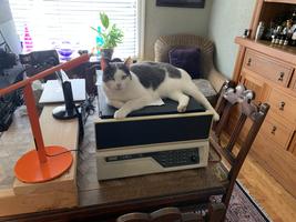
PDP-11/34
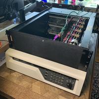
Tue 09 March 2021 by Fritz MuellerThis spring I worked on repair/restoration of a friend's PDP-11/34. The system was in fairly good shape, but missing a few bits and pieces and with the usual sorts of issues for 45-year-old kit. Started per usual with disassembly, cleaning, and inspection. The BA11-K chassis was in pretty decent shape; just a few scratches requiring some sanding and a little touch-up paint to inhibit future corrosion.
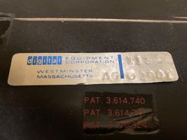
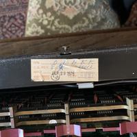
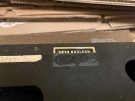
Date codes on the chassis and CPU cards are from 1976, but other components in the chassis are a bit of mix-and-match (a KY11-LB console interface and a third-party Monolithic systems memory board date from 1981, and a DL11-W SLU/RTC card is from 1977). Serial number is 2001. There is also a sticker for "OHIO NUCLEAR", which was an early manufacturer of CT devices.
Foam problems here were limited to a decayed air pre-filter at the front of the chassis and some padding on the cable retaining bar at the rear. A heat gun and a paint scraper are your friend for removing the leftover cellophane adhesive strips that were used to secure the foam. For the replacement pre-filter, I opted for 3M Filtrete carbon pre-filter sheet (part FAPF-UCTF2PAMZ) which comes in sheets large enough to cover the front of the chassis and is easily cut to size with scissors.
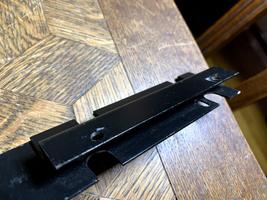
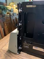
The front panel brackets ended up being a bit of a puzzle to reassemble -- I unfortunately failed to pay close attention to how exactly the lower fasteners were configured during disassembly. Most of the wisdom out in the restoration community seems to pertain to a newer, and much more convenient, version of these brackets (or the ones that arrived on this system were mismatched?) Here's a picture of the brackets that I have, and a shot of the arrangement I finally opted for for the flange-blinded mounting hole at the bottom of the chassis: machine screws driven from the back of the bracket with Keps nuts toward the front. I also added some 1/8" nylon spacers so the pre-filter could be extended across the entire front of the chassis, behind the brackets, and everything still remains square when tightened up. A serviceable replacement power knob was tracked down here.
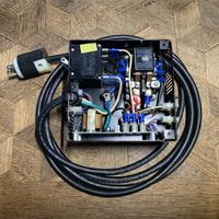
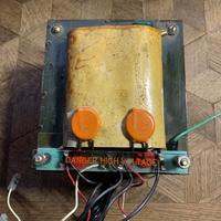
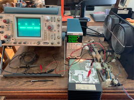
The BA11-K chassis has an integrated H765 power supply. The power-controller unit was in pretty good shape, but I replaced the line cord since the old one had some fairly serious nicks in its outer jacket. Also replaced cap C1 (50uF) which seemed to be drifting off value. Replaced the .1uF across-the-line caps mounted on the power transformer with modern X2 safety caps. The DC regulator modules (2x H744 +5V and 1x H745 -15V) were disassembled and cleaned. Reformed all the large electrolytics, then load tested the reassembled regulators individually. Nothing out of sorts here except the usual replacement of burnt out incandescent indicator bulbs.
I filled out the system with a near-side M9301 bootstrap-terminator (recent eBay purchase), some G727 "knuckle buster" grant continuity cards, and an M9302 SACK turnaround far-side terminator. New on this restoration was a UniBone Linux-to-Unibus bridge, used to emulate storage devices among other things (more on this in a separate article soon). Checked/adjusted NPR continuity on the backplane (continuity wire wraps in place for all slots except slot 9, to accommodate the UniBone). Module utilization as follows:
| A | B | C | D | E | F | |
|---|---|---|---|---|---|---|
| 1 | M7266 CPU control | |||||
| 2 | M7265 CPU data path | |||||
| 3 | M9301 boot term | M7859 console | ||||
| 4 | Monolithic Systems 303-0158 64 KiB memory | |||||
| 5 | M7856 serial / line clock | |||||
| 6 | G727 | |||||
| 7 | G727 | |||||
| 8 | G727 | |||||
| 9 | M9302 SACK term | UniBone | ||||
Connected up a VT100 to the serial card, and fired things up. Good signs of life from the front panel, but the machine immediately halted without producing a boot monitor prompt. Was able to reset the machine from the front panel, though, and then examine and deposit various memory locations from there.
Boot ROM memory locations were readable, and the contents looked correct. RAM addresses were generally readable and writable, but bit 10 appeared incorrect (sometimes always set; sometimes always clear). I was also able to successfully write to the console XBUF register from the front panel and see characters appear on the VT100.
A bus init from the front panel followed by manually punching in the boot ROM entry point produced a functional ROM monitor on the VT100. Deposits and examines to RAM done from the boot monitor produced results identical to those seen using the front panel (same bit 10 problem).
One of the cool features of the KY11-LB console is a maintenance mode that can run Unibus bus cycles on its own without a CPU. This gives a way to do limited testing of cards in isolation: just set up the M7859 on a powered, terminated backplane segment and plug in cards to be tested one at a time. Deposits and examines can then be done using the buttons and display on the front panel.
Interestingly, when running this way with just the console and memory cards in place the bit 10 errors were no longer apparent. Some other card was apparently corrupting bit 10 on the bus; by checking one at a time the problem was quickly isolated to the M9301 boot terminator card.
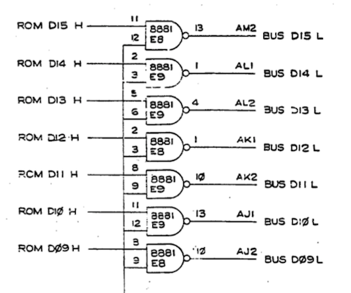
The M9301 drives the implicated bit onto the Unibus via an 8881 bus driver at position E9, as seen below. The signal coming in from the bottom here is ENAB DATA H, which is meant to enable these drivers only when the M9301 detects a valid address decode. Verified that data was being incorrectly driven on BUS D10 L at E9 pin 13, regardless of the state of pin 12, indicating a faulty driver. Pulled this, socketed, and replaced (with a compatible ECG 7439), and the bit 10 problem was fixed.
There was still some problem with auto-boot to the M9301 monitor, however; the monitor prompt would now begin to print at power up, but the machine would halt a few characters in. The front panel bus init plus manual jump to monitor entry point workaround was still working though, so put off further investigation of this issue until later.
At this point, given the workaround, the system was working well enough to begin loading and running MAINDEC diagnostics over the serial line with PDP11GUI. Relevant diagnostics, from the PDP-11/34 System User's Manual:
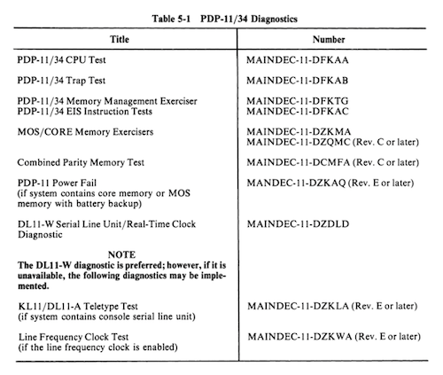
DFKAA, DFKAB, and DKFAC all ran without issue. DFKTG, DZKMA, and DZQMC all reported various errors, so time to look into the memory board.
The board is a Monolithic Systems 303-0158:
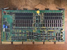
I could not find any information on the board on the internet, but much can be figured out by inspection and testing. First, the board is using 4116 (16Kx1) DRAMs, pretty usual for the era. There is space for 4 banks of 18; each bank would be 16K words (16 data bits plus two parity bits per word.) Here we see two banks populated, minus one of the parity chips. So we'd expect to see 32K words (64 KiB) mappable (or 28K words [56 KiB] with address translation disabled, to accommodate the 4K word [8 KiB] I/O page.) The missing parity chip is unlikely to cause any trouble in this application; in an '11/34, there is no memory parity support without the optional M7850 parity board installed, and this system does not have one.
One of the capabilities of the Unibone is to probe the full 18-bit Unibus address space, looking for active pages. These tests indicated that the memory board as configured was responding to the lower 128 KiB of addresses, even though only 64 KiB was populated. One would suppose that the mapped address range was configured via the DIP switches on the board. Some experimentation with various switch settings yielded the following:
| 7 | 6 | 5 | 4 | 3 | |
|---|---|---|---|---|---|
| 0 | . | . | . | . | 400000 |
| . | 0 | . | . | . | 200000 |
| . | . | 0 | . | . | 100000 |
| . | . | . | 0 | . | 040000 |
| . | . | . | . | 0 | 020000 |
| 4 | 3 | 2 | 1 | |
|---|---|---|---|---|
| 0 | . | . | . | 200000 |
| . | 0 | . | . | 100000 |
| . | . | 0 | . | 040000 |
| . | . | . | 0 | 020000 |
After setting the switches appropriately for the amount of memory physically present, memory test errors went away and the MAINDEC memory diagnostics (excepting parity tests) also ran successfully.
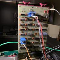
So the Last thing to fix was the problem with the boot monitor at startup. For this, the boot ROM card went back out on an extender so I could get at it with a logic analyzer.
A PDP-11 generates power down and power up traps, through location 024, based on transitions of the AC LO and DC LO Unibus signals. In handling this trap, the processor first reads the PC from location 024, then the PSW from location 026. Many PDP-11s had core memory or battery-backed RAM; this allowed for orderly recovery from power failure events.
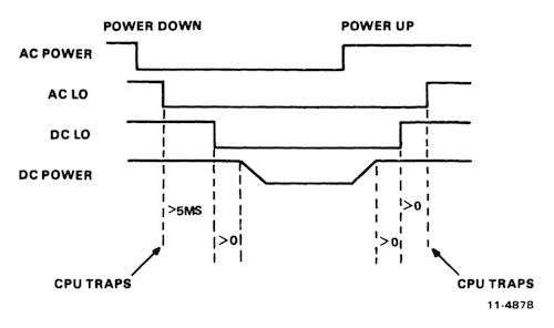
PDP-11 boot ROM cards like the M9301 or its younger cousin the M9312 use a hack to obtain control at boot. They monitor AC LO and DC LO, and when detecting a boot condition they jam higher order address bits on the Unibus for a the first couple bus cycles. This causes the PC and PSW to be fetched from locations within the address space of the boot ROM card. Here is most of the circuitry responsible for this:
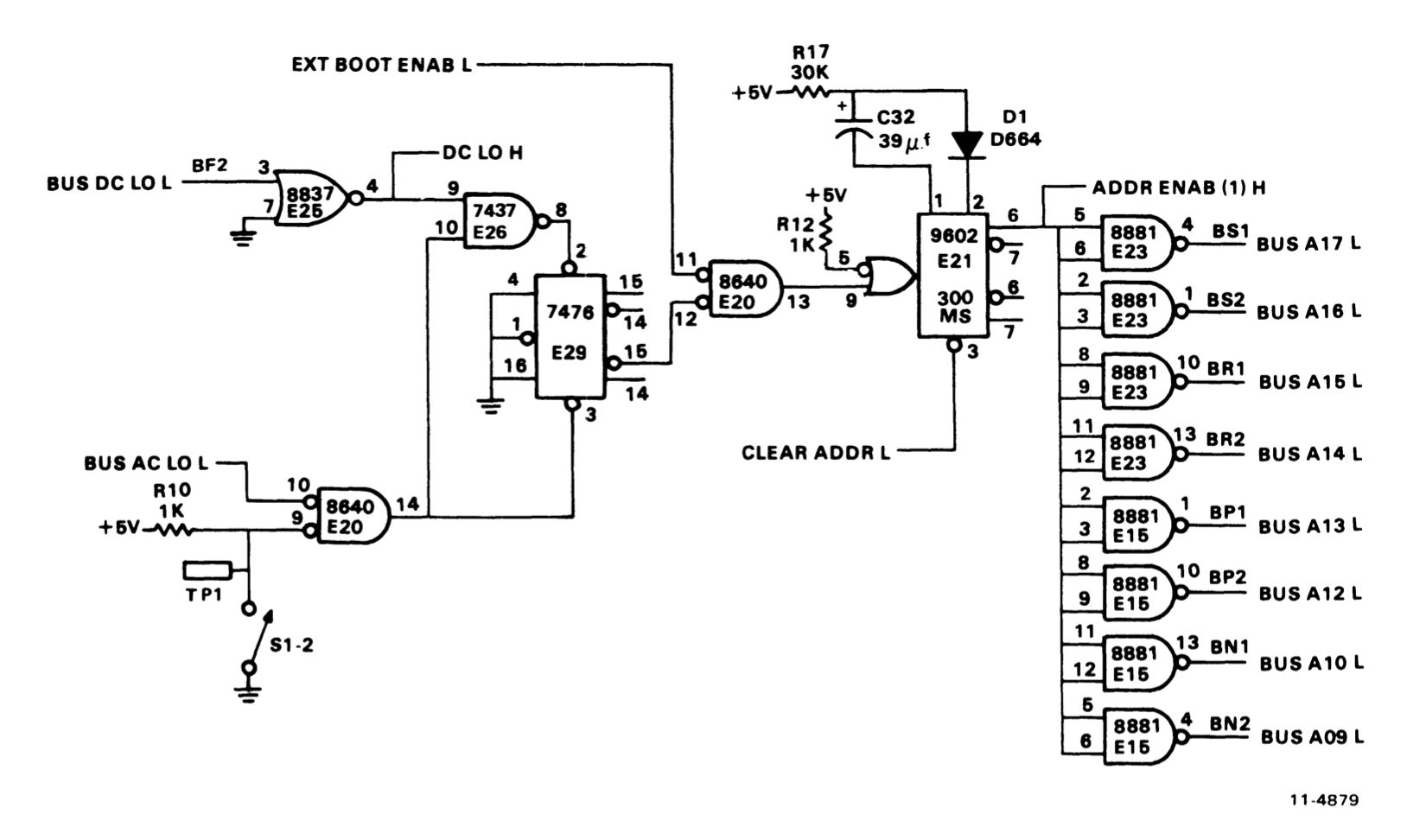
The bus drivers that jam the address bus are seen on the right. The central player here is E21, a 9602 one-shot. CLEAR ADDR L is supposed to arrive after the first two bus cycles (fetch of PC and PSW) and release the bus; the one-shot is set up to timeout after about 300ms and release the bus in any case.
On the logic analyzer, we can see an issue here:

MSYN delimits bus cycles mastered by the CPU. Here we can see that CLEAR ADDR L never arrives, and so the higher-order address bits remained jammed by the M9301 for the full duration of the one-shot timeout. This is okay for the first few instructions, which are executing out of the ROM anyway, but things quickly go awry...
Here is the circuitry responsible for CLEAR ADDR L:
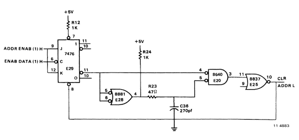
The desired pulse is mediated by 270 uF capacitor C36 in one leg of gate E20, so this is a good thing to check first, and... it is actually missing from the board! (Visible in the M9301 gallery picture above.) Replaced this cap, and now we are in good shape:

With this, the machine is fully repaired. Spent a little time with it, booting and running various operating systems from emulated storage on the Unibone card. Frieda also approves:
