PDP-11/45: Diagnostics XI - FP11 FPU, cont.
Sun 23 October 2016 by Fritz MuellerWrote some small test programs to investigate FP add/subtract. Turns out that single-precision add/subtract works fine, but double-precision results come back with some erroneous bits set in the fraction. Here's the test code I ended up using for troublshooting -- when executed on my machine, bits 24 and 25 end up incorrectly set in the result at D3:
1 2 3 4 5 6 7 8 9 10 11 12 13 14 15 16 17 | 000000 AC0=%0
000001 AC1=%1
000000 .ASECT
001000 .=1000
001000 170011 START: SETD ;SET DOUBLE PRECISION MODE
001002 172467 000014 LDD D1,AC0 ;FETCH FIRST ADDEND FROM D1
001006 172567 000020 LDD D2,AC1 ;FETCH SECOND ADDEND FROM D2
001012 172100 ADDD AC0,AC1 ;ADD THEM (RESULT IN AC1)
001014 174167 000022 STD AC1,D3 ;STORE RESULT TO D3
001020 000000 HALT
001022 040200 000000 000000 D1: .WORD 040000,000000,000000,000000 ;0.5
001030 000000
001032 040200 000000 000000 D2: .WORD 040000,000000,000000,000000 ;0.5
001040 000000
001042 000000 000000 000000 D3: .WORD 000000,000000,000000,000000
001050 000000
001000 .END START
|
So, the usual procedure: KM11 in the floating point slot, and FRL (where these bits are handled) out on extenders. First step is to verify the microcode sequencing with the KM11 and front panel, and it looks good. In particular, the FPU is sequencing through states ADD.04 and ADD.06 per expectation for double-precision, branching correctly for non-zero operands, and taking the equal exponents branch through ADD.24 (refer to page FLOWS 8 of the FP11 engineering drawings).
Next, stopped in state ADD.38, where the fraction addition occurs, and scanned the inputs and outputs of all the 74181 bitslice ALUs with a logic probe. Bit 28 of the A input to the FALU (E16 pin 2, refer to page FRLJ of the FP11 engineering drawings) is incorrectly set. This is arriving via the AR register.
The value in the AR register is originally fetched from the register scratchpad, then flows through QR, BR, and the FALU during microstates ADD.04, ADD.06, and ADD.02. Some more stepping and logic probe work showed that the fraction values are correct along these paths through these states. So it looks like AR itself may be at fault.
Set up the logic analyzer on E15, which is a 74194 shift-register that holds bits 28-31 of AR. It looks like it is indeed faulty:
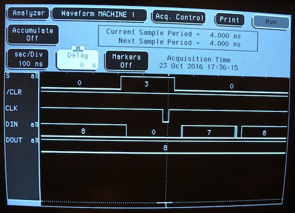
Here we can see what should be a broadside load: positive CLK edge, S0 and S1 both asserted, and inputs of all zeros. But the output sticks brokenly at 8. Pulled this shift register, soldered in a socket, and put a replacement and a couple of spares on order. All for now, until the parts arrive.