PDP-11/45: Some more floating point trouble
Sat 21 November 2020 by Fritz Mueller[A catch-up article, documenting events of April/May 2020]
In late April, I offered to give a video demonstration of the '11/45 to some interested work colleagues. Since I hadn't had it on in a while, I fired it up to make sure everything was still in working order. The machine behaved well from the front panel and was able to boot both V6 Unix and RSTS V06C. Great! Typed a very simple demo program in to RSTS (print a multiplication table) and that ran, but produced some very strange results. Uh oh...
Asked RSTS to PRINT PI, and it spat out a value somewhere around 3.7... :-)
So, time to try the floating point MAINDECS... Sure enough, failures all over the place, starting with the very first diagnostic in the floating point suite, CFPAB0. This diagnostic covers utility operations like LDFPS/STFPS, SETI/SETL, SETF/SETD, etc.
I do not have listings for the diagnostics in this suite, but it is usually simple enough to reproduce failures with short toggle-in programs given the names and descriptions of the failing diagnostics. In this case, the following simple code to exercise an LDFPS/STFPS sequence from the front panel switches and lights showed that bits 10 and 11 of the floating point status/control word would come back erroneously toggled:
1 2 3 4 5 | 001000 170137 START: LDFPS @#177570 ;LOAD FPS FROM SWITCH REGISTER
177570
001004 170237 STFPS @#177570 ;AND STORE BACK TO DISPLAY REGISTER
177570
001010 000773 BR START ;REPEAT
|
First things first, check power to the FPU and its clock; these look fine. Next, plug the KM11 into the floating point slot and check the FPU microcode sequences while executing LDFPS and STFPS instructions. These also look fine:
-
For
LDFPS @#177570I seeRDY.00,RDY.10,RDY.20,RDY.30,RDY.70,LD.50 -
For
STFPS @#177570I seeRDY.00,RDY.10,RDY.20,RDY.30,RDY.80,STR.30,STR.08
Most of the data paths of interest regarding the FPS register are on the fraction low (FRL) board, so this goes out on extenders so the microcode can be stepped and gate-level logic inspected with a logic probe.
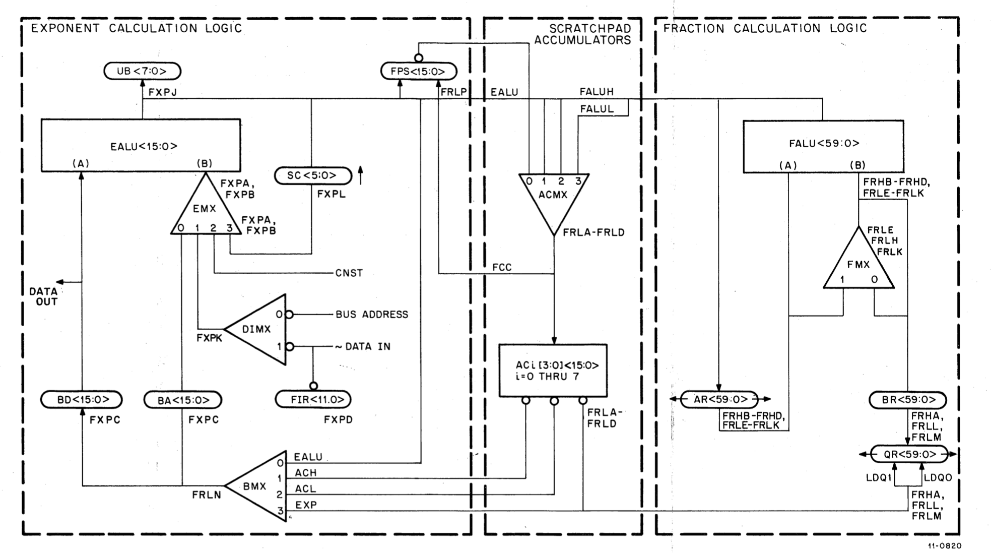
Here is the block diagram of data paths in the FPU, for reference in discussion below:

FP11-B data paths
So, one thing to note with regard to the FPS register is that it is gated through the ACMX multiplexer and
written into scratch pad register AC7[0] during microcode state RDY.00 which is the first state in the
common prolog of every FPU instruction:

FP11-B microcode prolog
Stopping in state RDY.00 and examining the ACMX inputs, selects, and outputs for bits 10 and 11 immediately
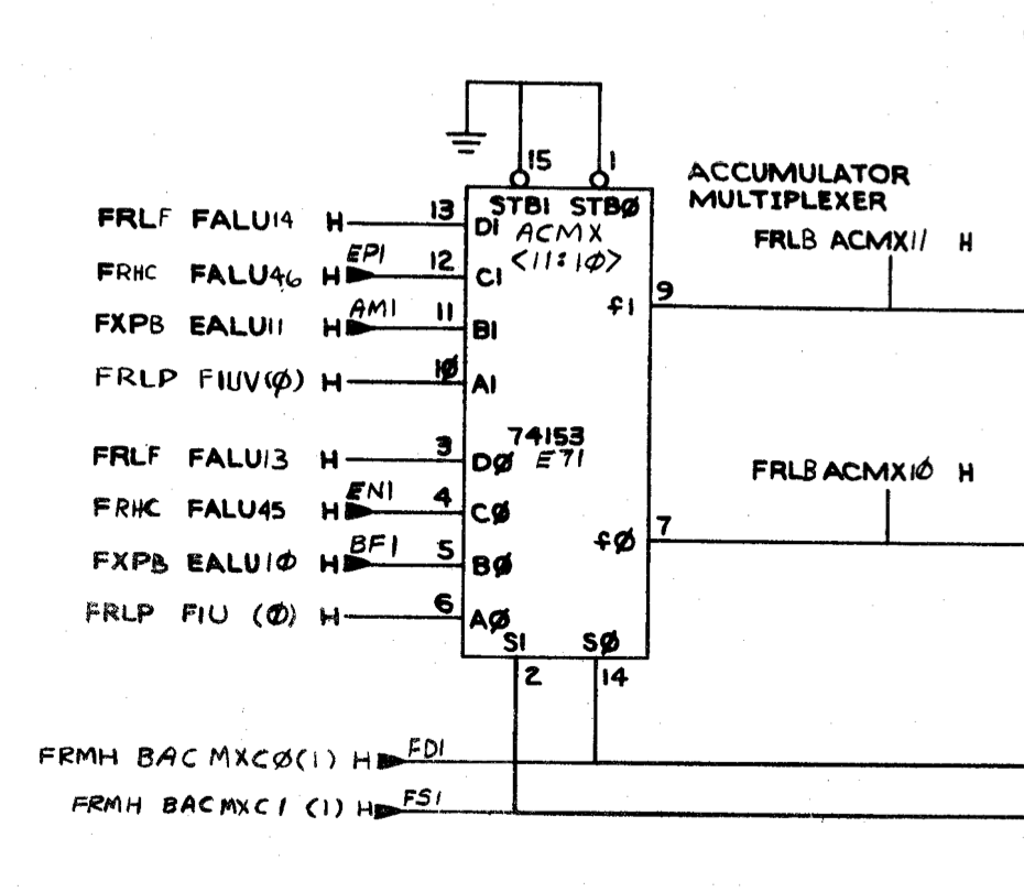
reveals a problem. These bits of ACMX are implemented by a 74153 dual 4-input mux, E71 on sheet FRLB of the
FP11-B engineering drawings:

FP11-B ACMX <11:10>
Inputs from the FPS register on pins 6 and 10 appear correct, as do the selector signals on pins 14 and 2. But outputs on pins 7 and 9 appear to be inverted. So E71 appears bad. Pulled this, socketed, and replaced. After this fix, LDFPS/STFPS function correctly in the toggle-in test program, and MAINDEC CFPAB0 passes.
Not out of the woods yet, though... Progressing down the sequence of MAINDECS, diagnostic CFPDC0 (add/subtract) now fails :-( For this, we bring back the simple "add two floats" diagnostic used during previous FP11 debug:
1 2 3 4 5 6 7 8 9 10 11 12 13 14 15 16 17 | 000000 AC0=%0
000001 AC1=%1
000000 .ASECT
001000 .=1000
001000 170011 START: SETD ;SET DOUBLE PRECISION MODE
001002 172467 000014 LDD D1,AC0 ;FETCH FIRST ADDEND FROM D1
001006 172567 000020 LDD D2,AC1 ;FETCH SECOND ADDEND FROM D2
001012 172100 ADDD AC0,AC1 ;ADD THEM (RESULT IN AC1)
001014 174167 000022 STD AC1,D3 ;STORE RESULT TO D3
001020 000000 HALT
001022 040200 000000 000000 D1: .WORD 040000,000000,000000,000000 ;0.5
001030 000000
001032 040200 000000 000000 D2: .WORD 040000,000000,000000,000000 ;0.5
001040 000000
001042 000000 000000 000000 D3: .WORD 000000,000000,000000,000000
001050 000000
001000 .END START
|
Sure enough, this is producing incorrect results. The microcode flows for add/subtract/compare are a bit more
involved than the simple load/store sequences above. The sequence starts with common prolog RDY.00,
RDY.10, RDY.20, RDY.30, same as above. The first fork after RDY.30 goes to RDY.60, since
add/subtract/compare are "no memory class" instructions (FP accumulator register operands only). The second
fork after RDY.60 takes us to ADD.00 on sheet FP11 FLOWS 8.
The left side if FLOWS 8 is a decision tree for zero operands and/or whether or not we are executing a compare
instruction. Traversal of these states sets up fraction and exponent operands and, if necessary, a comparison
of operand exponents in the EALU. In our case (addition of two double-precision non-zero operands), the
sequence is: ADD.00, ADD.04, ADD.06, ADD.02, ADD.08, ADD.12.
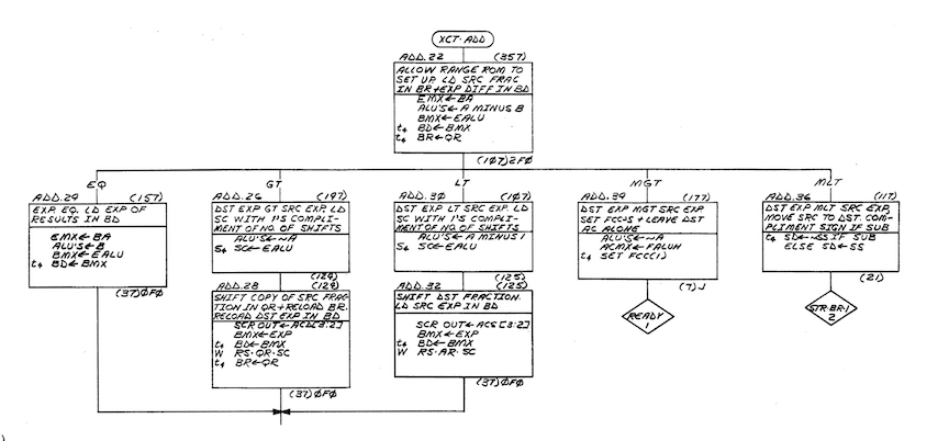
We then end up at state ADD.22 at the top of the right side of FLOWS 8. The previously set up exponent
difference is used to index into a 256x4 "range ROM"; output bits from this ROM inform the subsequent
microcode fork which determines which operand shift, if any, to apply before the upcoming fraction ALU
operation.

Here a problem is evident. We should fork to ADD.24, for equal exponents, but instead we end up add
ADD.30, for destination exponent less than source exponent. Putting the FXP board out on the extender and
pausing in this state, the operands and operation codes on the EALU bit-slices appear to be correct, but
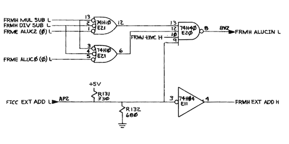
signal FRMH ALU CIN L is erroneously asserted at E34 pin 7 (sheet FXPA). This extra carry (borrow, really,
since the operation is a subtract) into the least significant bit-slice causes the EALU output to be -1
instead of 0.
Moving back to the source of this signal on the FRM board, it turns out that FRM E20, a 74H40 dual quad-input NAND, is outputting an invalid logic level at pin 8. Pulled this, socketed, replaced, and the problem appears to be fixed.

After this second repair, the full suite of FP11-B diagnostics is passing again. And RSTS/E has a much less
fanciful interpretation of PI...