PDP-11/45: Parity error handling
Mon 25 May 2020 by Fritz Mueller[A catch-up article, documenting events of Jan/Feb 2019.]
At the end of the previous article, a bunch of repairs had been made to my MS11-L memory board. The associated MAINDEC diagnostic ZQMC was able to run cleanly but only with parity tests disabled. When parity tests were enabled, the parity fault LED on the MS11 would light (expected) and the machine would halt with ADRS ERR lit (unexpected...)
So the first step is to read and research how memory parity handling is implemented on the KB11-A CPU. Immediately here we run into some trouble:
-
The 1973 edition of the 11/45 Processor Handbook has a section 2.5.6, "Memory Parity", which states: "Parity errors cause the Central Processor to either trap through location 4 or to halt." There is also an Appendix E, "Memory Parity", which details CSRs for parity memory:

It is stated there that there are 16 of these, at addresses 772110-772146, each corrsponding to an 8K word block of address space.
By the 1976 version of the processor handbook, however, all of this information had been expunged. The new Appendix A, "UNIBUS Addresses", lists range 772110-772136 simply as "UNIBUS memory parity". Here, trap 4 is listed as "CPU errors", and trap 114 is listed as "Memory system errors". All subsequent revisions of the handbook state unambiguously that parity errors generate a trap 114.
-
What do the KB11-A processor maintenance manuals have to offer? Paragraph 7.7.7 of the 1972 KB11-A maintenance manual states:
A Parity error on the Unibus A is indicated by BUSA PA L high and BUSA PB L low. The parity error causes UNI PERF (Unibus parity error flag) to be set when MSYN is cleared. UNI PERF (1) L asserts UBCB PARITY ERR SET L during the pause cycle, which sets the console (CONF) flag and halts the CPU.
The semiconductor memory control EHA and EHB (enable halt) flip-flops may be set under program control to assert SMCB PE HALT if a parity error is detected. This input also asserts UBCB PARITY ERR SET L, which sets the console flag and halts the CPU. Thus, if either a Unibus A parity error or SMCB PE HALT L is asserted, the processor will be vectored to trap when the CONT switch is pressed.
Note that this text addresses how the CPU handles detected parity errors in both Unibus (first paragraph) and fastbus (second paragraph) memory systems. Unibus parity errors are stated to set the CONF flag and halt the CPU, just as I am seeing on my system... Fastbus parity handling (halt first vs. direct trap) can further be mediated by EHA and EHB, called out here to drawing SMCB in the MS11-B/C fastbus semiconductor memory print set.
But here, too, by the time we get to the later revision 1976 KB11-A,D maintenance manual, this information is revised. The updated description makes no further mention of CONF, halting, or halt control, and seems to imply that all reported parity conditions trap directly through 114.
-
How about contemporaneous memory systems? The MS11-B/C solid state memory systems released with the 11/45 (note: not what I'm running; I have the much later MS11-L) consisted of either MOS or bipolar memory matrices with an associated controller card (the M8110). These supported both Unibus and fastbus interfaces. Here, in the 1972 schematics, we see the implementation of the EHA/EHB halt control bits, mentioned above, in the upper left of sheet SMCB:
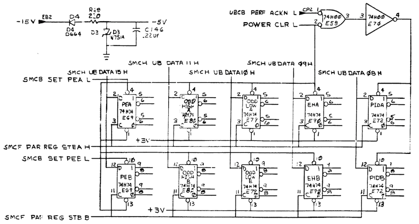
We can see the bit assignments here match the CSR layout from the 1973 processor handbook, and the associated MS11 maintenance manual from 1973 also describes them in its table 3-12:
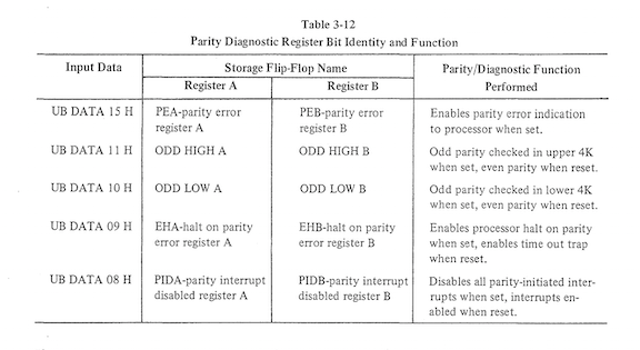
And once again, by the 1974 revision of the same maintenance manual, no surprise: descriptions of the halt control bits have been expunged from table 3-12. Okay, we're starting to get a consistent picture here...
I don't know much about the core memory systems that were configured with the early 11/45s? It would be interesting to know if anything other than the MS11-B/C ever supported this older CSR layout.
-
Let's have a look at the KB11-A engineering drawings themselves. The set I've been using during my restoration dates from 1974. The first, most obvious, place to look is trap vector generation; this is accomplished on the lower left of drawing DAPE:
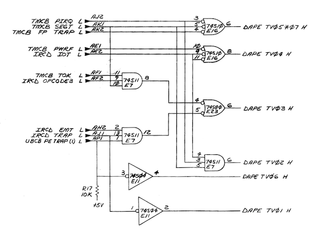
This small combinational net feeds trap vector bits to the K1MX constant multiplexer. One non-obvious wrinkle noted elsewhere on the drawing: vectors generated for reserved instruction (004), EMT (014), and TRAP (016) are further left-shifted, downstream, by microcode (state RSD.10, drawing FLOWS 12) to result in 010, 030, and 034 respectively. That's not strictly relevant to the discussion at hand, but might be helpful if pondering the logic implemented in the diagram above.
This drawing is definitely from the "post 114" era. On a parity error, we'll have ~IOT and ~PIRQ and ~SEGT, together driving TV02 high; that's our traditional vector 004. But here we also see UBCB PE TRAP (1) L, active low, entering from the left. When driven low, we'll get TV03 and TV06 high as well, all together generating vector 114.
Here we can see some clues, too, of how the change to 114 might have been bodged in: as drawn, TV01, TV02, TV03, TV04 and TV05*07 proceed nicely in order from bottom to top. But TV06, needed by the change as the most-significant "1" in "114", looks like it was just wedged in out of order on the drawing... Presumably, it makes use of a previously unused section of hex inverter E11. The change to activate TV03 here as well would have been a cut/jump at the inputs of E7.
And sure enough, here we see differences with my actual hardware! Here's part of the layout of module DAP from the '74 engineering drawings, and a snap the same corner of my DAP spare which is same as the one I'm currently running in the machine:
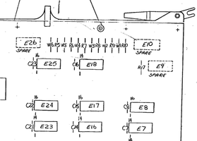
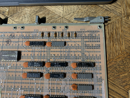
Note particulary that R17, a pullup for UBCB PE TRAP (1) L, is missing on my board. A little further work with the beeper shows that on my boards E7 pin 1 is connected directly to E7 pin 13, and is not connected to edge connector AP1. E11 pin 3 appears to be NC. Furthermore, examination of the backplane shows that there is no wire wrapped in place at DAP AP1 to deliver signal UBCB PE TRAP (1) from the UBC board. So, I think I can conclude we're not looking at a bug or component failure here; my 11/45 simply pre-dates the change from vector 4 to vector 114.
-
Okay for the vector, but what about the halt behavior? Here, the text quoted earlier from the 1972 KB11-A maintenance manual has our clue where to look. The parity derived signal eventually resulting in the halt on either Unibus or fastbus parity error is UBCB PARITY ERR SET L (note "SET" in the signal name here, don't confuse with UBCB PARITY ERR L...) The 1974 drawings imply that a fastbus parity err, but not a Unibus parity error, will halt the machine, in conflict with this text. But looking here, we see another bodge clue: the hookup at E68 pins 4 and 5 as drawn looks a little suspicious...
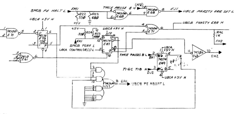
And indeed, on my hardware, E68 pins 4 and 5 are not connected together; rather, E68 pin 5 is connected to E79 (Unibus parity error flag) pin 5. So, Unibus parity errors will also halt this version of the 11/45 hardware, by design.
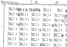
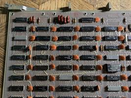
Some other differences related to parity are also apparent looking at my version of the UBC board. E57, seen above generating UBC PE ABORT L, is not populated. This seems related to some further refinement of abort sequencing, but the cirumstances surrounding the need for this aren't clear to me at this point. Also, jumper W1 and associated logic to entirely disable Unibus parity error detection are not present:
So, what does all this mean? Well, for one thing, there apparently isn't anything actually in need of repair here -- as far as I can tell, this version of the hardware is functioning per design, such as it is.
And as it turns out, with a now properly repaired MS11-L, actual parity errors are few and far between (I've yet to see any that weren't intentionally created by diagnostics.) According to Noel, stock Unix V6 doesn't do anything whatsoever with parity. RSTS/E V06C boot code seems to be properly probing and identifying the CSR on my MS11-L. And good old RT11 has seemed happy enough in the past. So I just may not need a totally up-to-date parity implementation on my machine.
There is still the issue of more broadly tracking down and implementing outstanding ECOs for this machine. I have so far had limited success in locating these (more on this next time!) I'm certainly equipped here to implement field cuts and jumps, but it might get tricky to track down newer versions of boards for any ECOs that involved total swaps to updated etches. In any case, in the absence of complete information on the ECOs I'm hesitant to cherry pick changes such as those identified here unless I am really blocked without them; better by far not to leave the machine in an undocumented "in-between" state.
Footnotes: a lot of the discovery documented here took place in the context of the enthusiast community on the cctalk mailing list, and also in private communications. Noel Chiappa and Paul Koning were both particularly generous with their time (thanks, guys!) Here are some interesting related bits that didn't fit directly in the narrative above, for completeness and for future reference:
-
On RSTS parity CSR sniffing, from Paul:
From: Paul Koning
To: cctalk
Subject: Re: PDP-11/45 RSTS/E boot problemFritz Mueller wrote:
There is a lot of inconsistent and incomplete information in the documentation about memory CSRs. They appear to come in different flavors depending on memory hardware; some of the earlier ones support setting a bit to determine whether parity errors will halt or trap the CPU, while some of the later ones (like my MS11-L) simply have "enable" and don't distinguish between halt and trap. I'm curious how OS init code sniffs out what memory CSRs there are, determines their specific flavors and, in a heterogeneous system, determines how much address space is under the auspice of each CSR? Maybe Paul and Noel can comment here wrt. RSTS and Unix respectively?
I quickly skimmed some RSTS INIT code (for V10.1). Two things observed:
1. At boot, INIT determines the memory layout. It does this by writing 0 then -2 into each location to see if it works. If it gets an NXM trap (trap to 4) or a parity trap (trap to 114) it calls that 1kW block of memory non-existent. For the case of a parity error, it tells you that it saw a parity error and is disabling that block for that reason.
2. In the DEFAULT option (curiously enough) there is a routine that looks for up to 16 parity CSRs starting at 172100. This happens on entry to the memory layout option. You can display what it finds by using the PARITY command in response to the "Table suboption" prompt.
It checks if the bits 007750 are active in the parity CSR, if so it takes that to be an address/ECC parity CSR. It figures out the CSR to memory association by going through memory in 1 kW increments, writing 3, 5 to the first 2 words, then setting "write wrong parity" in each CSR (007044), then doing BIC #3,.. BIC #5,... to those two test words, then reading them both back. This should set bad parity, and it scans all the CSRs to see which one reports an error (top bit in the CSR). If no CSR has that set, it concludes the particular block is no-parity memory.
I probably got some of the details wrong, the above is from a fast skim of the code, but hopefully it will get you started.
My machine currently has one MS11-L, which has the newer CSR layout referred to by Paul above (different than the much older MS11-B/C CSR layout depicted at the top of this article; see MS11-L docs for further details). RSTS init defaults->memory->parity on my system reports (correctly):
0K: 00000000 - 00757777 ( 124K) : 00
Presumeably, RSTS carries out this identification activity with the CSR report enable bits off, and the CSR error bits still function correctly in these circumstances; otherwise, per above, my machine would summarily halt during this process!
-
Noel, in some of his research, found Deeper magic from before the dawn of time re. evolution of the Unibus parity implementation before the era of the start of this article, bridging back to the KA11 (11/20) CPU. Quite interesting!
From: Noel Chiappa
Subject: Change in UNIBUS parity operation (Was: PDP-11/45 RSTS/E boot problem)
To: cctalkEven better, it claims to be able to control whether the memory uses odd or even parity! (How, for UNIBUS memory, I don't know - there's no way to do this over the UNIBUS.
So this really confused me, as the UNIBUS spec says parity is wholly within the slave device, and only an error signal is transferred over the bus. E.g. from the 'pdp11 peripherals handbook', 1975 edition (pg. 5-8): "PA and PB are generated by a slave ... [it] negates PA and asserts PB to indicate a parity error ... both negated indicates no parity error. [other combinations] are conditions reserved for future use."
The answer is that originally the UNIBUS parity operation was different, and that sometime around the introduction of the PDP-11/45, they changed it, which is apparently why Appendix E, about parity in the /45, says what it does!
I found the first clue in the MM11-F Core Memory Manual (DEC-11-HMFA-D - which is not online, in fact no MM11-F stuff is online, I'll have to scan it all and send it to Al); I was looking in that to see if the parity version had a CSR or not (to reply to Paul Koning), and on the subject of parity it said this: "The data bits on the bus are called BUS DPB0 and BUS DPB1." And there is nothing else on how the two parity bits are used - the clear implication is that the memory just stores them, and hands them to someone else (the master) over the bus, for actual use.
Looking further, I found proof in the "unibus interface manual" - and moreover, the details differ between the first (DEC-11-HIAA-D) and second (DEC-11-HIAB-D) editions (both of which differ from the above)!
In the first, Table 2-1 has these entries for PA and PB: "Parity Available - PA ... Indicates paritied data" and "Parity Bit - PB ... Transmits parity bit"; at the bottom of page 2-4 we find "PA indicates that the data being transferred is to use parity, and PB transmits the parity bit. Neither line is used by the KA11 processor."
(Which explains why, when, after reading about parity in the MM11-F manual, I went looking for parity stuff in the KA11 which would use it, I couldn't find it!)
In the second, Table 2-1 has these entries for PA and PB: "Parity Bit Low - PA ... Transmits parity bit, low byte" and "Parity Bit High - PB ... Transmits parity bit, high byte"; at the top of page 2-5 we find wholly different text from the above, including "These lines are used by the MP11 Parity Option in conjunction with parity memories such as the MM11-FP."
I looked online for more about the MP11, but could find nothing. I wonder if any were made?
This later version seems to agree with that Appendix E. I tried to find an early -11/45 system manual, to see if it originally shipped with MM11-F's, but couldn't locate one - does anyone have one? The ones online (e.g. EK-1145-OP-001) are much later.
It's also interesting to speculate about reasons why these changes were made; I can think of several! :-)
All for now!