Atari Tempest repairs
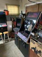
Mon 01 March 2021 by Fritz MuellerSome friends of mine own vintage arcade games. Two of them had Atari Tempest machines (one a full-size upright, one the rather more rare "cabaret") that had ceased to play, so I offered to look at them both if they could be dropped off here at my home. Some time later, and here they are in the garage (the Space Duel upright in the background is my own):
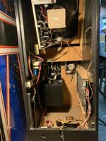
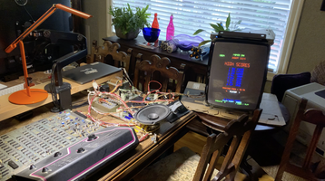
Overall, these are not too complicated, and pretty easy to work on:
-
There is a straightforward linear supply in the bottom of the cabinet, known as the "brick", which provides +10.6 VDC and 50, 36, and 6 VAC.
-
A separate card, the "AR2" (downstream of the brick, also linear), derives +12, +/-5, and +/-22 VDC, as well as hosting audio power amplifiers for game sound.
-
The "brains" of the game are a control board with a 1.5 MHz 6502A processor, ROMs, RAM, and GPIO for settings DIP switches, coin door etc. Since Tempest is a vector game, a fair bit of the control board is also dedicated to vector generation; Tempest uses an "analog vector generator" where vectors are swept by analog integrators with rate inputs fed by DACs. The control board has a daughter-card which has 4x AMD2901 bit-slice ALUs to assist the 6502 with math, and a couple of custom Atari chips ("POKEYs") for sound sound generation and game control input.
-
Last, there is a color vector CRT, the WG6100. This has X and Y deflection amplifiers similar to an oscilloscope, and accepts RGB inputs for color/intensity.
These games are quite common, so all of these components have well-understood failure modes; you will find these discussed in various arcade repair online forums and FAQs. The stuff I always look for:
-
Brick: There is a large electrolytic, known as "big blue", which is the primary filter for the +10.6 VDC. If it is still the '80s original, it is probably worth a check. Modern drop-in replacements are available for ~$15 USD.
There is also a fuse block wired in with crimp quick-disconnects. They are problematic because they may oxidize or rattle loose, causing increased resistance and eventually thermal runaway as the currents here are in the multi-amp range and the brick is located at the bottom of the cabinet where air circulation is not great. It is not uncommon to find toasty wiring and/or melted plastic fuse blocks; if doing repairs in this area I'll generally just clip off the quick disconnect connectors entirely and solder the wires down directly to the fuse block tabs to avoid future reliability issues.
-
AR2: Common fails here are also generally thermal issues. Recap kits for these boards are available from the arcade parts houses, but in my experience aren't often required. Each of the supplies on the AR2 is pretty easy to bench test, but make sure you test with at least a minimal load in place as some of the linear regulators here will behave unpredictably when unloaded. I've never personally seen a failure of the integrated audio amplifiers on the AR2, so I generally don't bother to test them up front; if I have an audio problem with the game I will come back and give them a look later.
The +5 VDC supply here works with a remote sense, which is a matter of some controversy. There can be an appreciable (and variable between cabinets) voltage drop from the AR2 to the game boards over the molex connectors, wiring harness, and game board edge connectors in between. Atari seems to have gone for a remote sense design to automatically compensate for this. The problem is that it is not uncommon for the board edge connectors to loosen over time and/or accumulate dust and oxidation, increasing resistance, and leading to another thermal runaway situation as the supply keeps upping the juice to overcome ever-increasing resistive drop. It is not uncommon to see toasted wiring, toasted AR2, and/or even burnt board traces.
Some techs advocate short circuiting the remote sense at the AR2 (known as the "sense mod") with the argument that it is less destructive to fail into a game-board-under-voltage condition than to fail into an over-current-until-something-burns situation. Others insist the original design is fine as long as board and harness connections are well maintained. I tend to leave things stock unless there is evidence of a problem. If a particular cabinet looks like a chronic +5 burner, though, I'll go ahead and implement the sense mod as well as repairing/replacing the board edge connector; I also add some additional beefy supply and ground wires directly between the AR2 and voltage test terminals on the game boards to shed load off the board edge connector.
For a toasted +5 supply, check Q3, the TO3 series pass transistor on the large heat sink. Sometimes this fails just because of poor thermal connectivity with the heat sink; replacing the stock mica insulator with a silpad and a very thin coat of fresh thermal grease can help here.
-
WG6100 color vector display: This is its own odyssey :-) Lot's of good info on trouble-shooting and repairing these is available on the web. In particular, there is a low-voltage supply section on the deflection board which is quite failure-prone. There are drop-in replacement supply circuits available; you pull all the components in the original section and solder in a small pre-fab daughter board in their place (google "LV-2000"). This upgrade increases the long-term reliability of the WG6100 to such a significant extent that I always opt to install one of these if not already present.
Next most common are fails with the through-hole cable pin connectors. Solder connections here break from repeated mechanical stresses of plugging and unplugging connecting cables, and for some reason the original factory solders here seem pretty shoddy. Always worth giving these a reflow with some fresh solder.
TO3 deflection transistors are mounted off board on the monitor chassis, using the chassis as one big heat sink. These are frequently a casualty of some other cascading failure in the monitor. Flying leads to the sockets holding these transistors sometimes break loose from mechanical stresses, or the old sockets may fail, or mica insulators may develop shorts to the chassis (silpad etc. treatment is generally a good idea here too.)
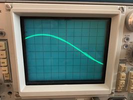
One thing to be careful of here is that there seem to be a lot of counterfeits of these particular transistors (2N3716/2N3792) on the market. Counterfeits will mostly work, but can exhibit some strange instabilities at cross-over which can manifest as ringing and parasitics in the deflection amplifiers causing "wiggly" vectors that can be difficult to troubleshoot (see pictures from another WG6100 monitor repair immediately below). Make sure to order from one of the larger, more reliable, parts houses for these.
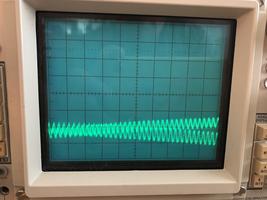
The HV supply in these monitors seems particularly hard on its electrolytic caps; I've seen more cap failures in these HV supplies than anywhere else in these games. Generally worth just doing a recap kit on the HV board if the caps don't look fresh when you get there; it can help improve the stability and appearance of the monitor a lot. After achieving correct and stable B+ on the HV supply, if there still seem to be brightness problems, check C503 on the neck board and refresh if necessary.
-
Game boards: there are eight small PCB mount potentiometers for trimming the analog X/Y outputs. The stock parts are open-frame and seem to collect dust and get twitchy and intermittent (open wiper contacts here can be a cause of loss of video output). I generally just go ahead and freshen these before starting in on the boards, as I hate working with them when they are intermittent/unreliable.
Solder fails in the large interconnect between the mother and daughter boards are also common; these are also worth a preemptive reflow.
These two games from my friends were no exception to the above, and after working the standard stuff for both I had two working bricks, two working AR2s, two working monitors, and one working board set. The second board was producing no output of any sort, didn't appear to respond to its reset switch, and required further investigation.
Okay, like any microprocessor project, start with power, clock and reset... Power looked fine. Clock, not so much. Here's the clock circuit:
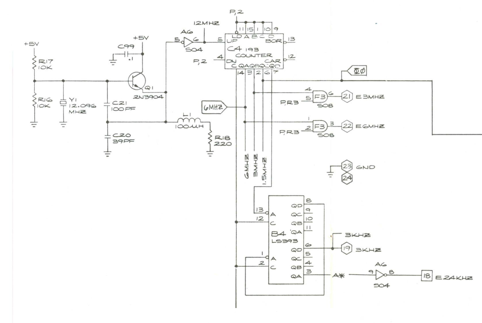
12 MHz crystal with some pulse shaping scoped out fine. Master clock then goes to counter chip C4 to divide down to various derived clocks, including the crucial PHI0 for the 6502. Turns out this counter wasn't counting because its clear input (pin 14, seen arriving from below) was being continuously driven. That input comes from the watchdog circuit and power on reset circuit:
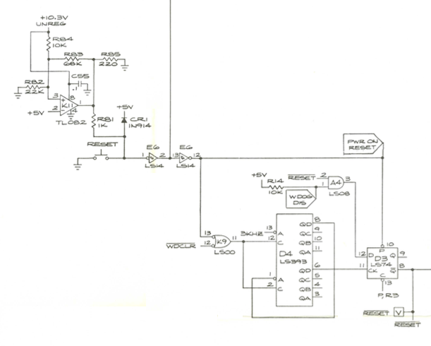
Reset was continuously asserted here because of a dodgy Molex connector which was not delivering +10.6 VDC to TL082 K11 at the left. After fixing this, the machine came out of reset, the reset button was working, and there were signs of activity on the 6502 data and address busses. But the game wasn't really running, and the watchdog was repeatedly timing out, so it seemed to be executing incorrect code.
Pulled the game ROMs, and used a burner/reader to verify their checksums against published values from the arcade game forums (all good). Checked for shorts around the sockets (found none) and reseated the ROMs. Pulled the 6502 and manually drove address bus lines to verify proper operation of the ROM address decoders (all fine). Okay, so time to watch the microprocessor busses on a logic analyzer and see what's going on...
Now, I love my old HP 1660 logic analyzer, lots, but a friend had recently loaned to me a compact 34-channel USB logic analyzer (Intronix LA1034) to see if I might be interested in buying it, and I decided to give it a try for this project. It was pretty easy to probe up the 6502 with a DIP clip, and the software for the analyzer (Windows only) installed and ran without difficulty on my Windows 10 VM.
When the 6502 comes out of reset, it fetches its reset vector from locations FFFC and FFFD, then jumps to that address. Looking at the Tempest ROM listings, the reset vector is supposed to point to address D93F. Watching the 6502 address and data busses, and setting a trigger for address FFFC, we can immediately see a problem:

Here, the top line is the 6502 address bus, and the middle line is the 6502 data bus. The bottom line is the output on the ROM bus, upstream of the driver which gates it onto the data bus.
The 6502 comes out of reset, and attempts reads of locations FFFC and FFFD, as visible on the address bus, but it is receiving incorrect data (C82E vs. the expected D93F). It then jumps to the incorrect address, and from that point onward we are off in the weeds. Interestingly, we can see here that the ROM is, in fact, presenting the correct data.
So the first thing was to try replacing the bus driver between the ROM and the 6502 data busses, but this did not fix the issue (sadness). Besides this and the 6502 itself (already verified by swap with the other working game board) there are only two other drivers on the processor data bus: H2, leading to the daughter board, and F2 leading to the RAM bus. ROM bus seen entering here from the bottom:
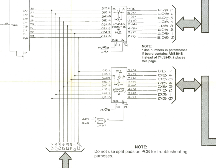
One of these two drivers must be dragging down a couple of lines on the data bus; nothing to do here but try swapping them out one by one. Tried F2 first, and got lucky! Game code began to run, and the game board produced vector outputs. Correct reset sequence after the fix:

From this point forward, just wrap-up:
-
The X positions on the ends of some vectors on the second game board set looked slightly incorrect, beyond what could be adjusted with via the associated rate op-amp offset ("BIP", in Atari-speak) trimmer. This usually indicates a failing rate DAC. Replaced the X rate DAC on this board and the problem was addressed.
-
Various small mechanical repairs to the cabinets, replacement of bits of missing hardware, and cleanup of a hacked-up wiring harness on one of the machines.
-
The cabaret machine had a failed fluorescent tube fixture for its marquee light; after checking with the owner, pulled this and replaced with an LED fixture for greater reliability (I like this one, which is a 120v fixture that doesn't need a separate transformer or supply.)
-
Another upgrade I really like for Tempest machines is a set of brass bushings for the spinner (available here). These make the spinner quiet and smooth as butter.
All done now, and ready to be returned to their owners (after some extensive "burn in" play testing, of course! :-)