PDP-11/45: Power fixes and CPU debug
Mon 30 May 2016 by Fritz MuellerConnected up the aforementioned red wire hack to the new power harness, and verified +5V to slots 10 through 15. Console is no longer all address and data lights on, but basic console load address / examine / deposit operations are still not working. A random assortment of address lines seem stuck, different on each power cycle. About the only thing that reliably functions from the console is loading the two highest address bits from the switches immediately after a reset. Pulled the floating point unit, unjumpered the DD11 expansion backplane, and removed all peripherals except the M792 diode ROM; same (broken) behavior...
Scoped all the DC voltages, and did not notice any glitches. Pulled the H742s for some bench work: verified AC LO and DC LO signaling on both units, replaced a broken Mate-n-Lok connector on one of the units, blew out dust from all the 5V regulators and replaced their indicator bulbs with modern equivalent (CM7381). Sourced and put on order a modern equivalent (OL-6003BP) for the indicator bulbs on the -15V regulators.
Next steps will be to verify various Unibus signals on the backplane, then maybe play some swap games with CPU card spares to see if I can get closer to a working console as a starting point. All I have time for this weekend, though; sorry nothing new to see so no new pictures this time!
PDP-11/45: Initial Power On!
Sun 08 May 2016 by Fritz MuellerBeeped out the new harness to check for shorts or incorrect pins, then plugged in just the H742s and fired it up. All the DC regulator modules seem to be working, and I was able to trim them up to nominal voltages at the CPU end of the harness. The indicator lamps on all but one of the DC regulators seem to be burned out, though, so I put some new lamps on order (at last for the +5V regulators; a modern equivalent for the -15V regulators is tougher to find).
Given that success, I plugged in the CPU side of the harness, took a deep breath, and powered on! Hmmm. No detonations or smoke, but all data/address/mode lights lit (see below), which is not right... Front panel lamp test and data address mode switches and indicators are working though at least.
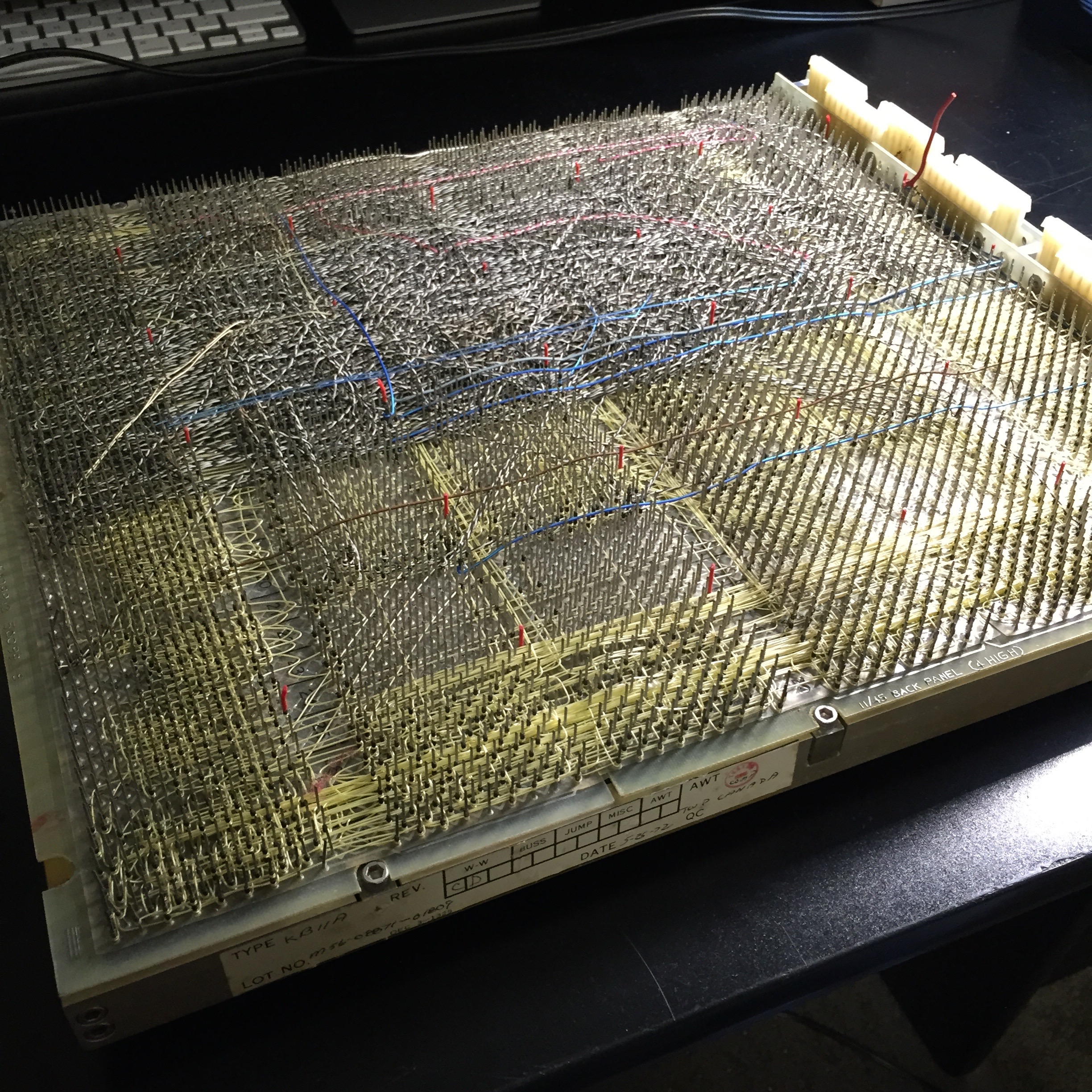
Some investigation on the backplane turned up no +5V to slots 10 though 15, which could be part of the problem. Ah, that's what the mysterious clipped red wire soldered to the backplane might have been about (visible in the top right here...) Sure enough, some inspection shows the corresponding trace on the backplane looks burnt! I could hack this red wire into my new harness I guess, but I'd rather remove it and try to repair the board trace with a shunt. So the backplane will have to come out. I guess that's what I get for not investigating the weird red wire and for not beeping out the power distribution on the backplane before mounting and populating it...
. Well, it's a start!")
PDP-11/45: Power Harness, continued
Sat 23 April 2016 by Fritz MuellerMoved the power modules and partial harness back over to the racks today, got everything remounted, finished and dressed the backplane terminations, and completed the inter-H742 connections.
I did not do the runs for the backplane memory to the lower H742, as I do not have any backplane memory. I probably won't ever have any, either: these memory options are specialized to the '11/45, are quite rare, and only cover part of the available address space. Additionally, they would require me to track down the details of a backplane ECO to do the corresponding parts of the harness correctly. The core and MOS memory that I do actually have are all system-unit options anyway.
Here are some pics of the in-rack wiring in progress, and a couple views of the finished harness. If you add up the capacity of the DC modules, you'll see that an '11/45 like mine (with floating point) is provisioned with +5V at 100 [sic] amps, and -15V at 20 amps. That's no joke of a power supply...


PDP-11/45: Power Harness
Sun 17 April 2016 by Fritz MuellerThe main bit I'm missing from the '11/45 is the power distribution harness; somewhere over the years this was misplaced, or maybe I accidentally gave it away along with some excess '11/40 parts. In any case, I haven't had any luck tracking one of these down (made extra difficult by the fact that my '11/45 is an early model which requires a slightly different harness than more recent models), so I'll have to build one myself from scratch.
Luckily the required harness is pretty well documented in the engineering print sets. The crimp pins are standard Mate-n-Lok still in production. Some of the connectors are out of production, but they haven't been too hard to track down.
Here are some pictures of the amassed wire of appropriate gauges and colors, connectors, crimp pins, and the start of the harness build on the bench:


PDP-11/45: Some parts from eBay
Sat 09 April 2016 by Fritz MuellerI've been keeping an eye on eBay and have collected a few more goodies: a DD11-D nine-slot expansion backplane, a fully populated (128K x 18-bit) MS11-L MOS memory board, and a couple of replacement BC08-R cables for connecting the console to the CPU cards. The MS11-L is a bit of a luxury; I am figuring it will be easier to deal with during bring-up than the core memory systems I have on hand. It will also be nice to run with a full address space.
Below is an updated shot of the CPU chassis with the expansion backplane installed, populated with bus jumpers, terminators, grant continuity cards, the MS11-L memory, a DL11 serial interface, and an M792-YB bootstrap ROM. I've gone ahead and slotted in the FPU in the first four slots, since the cleaned and refurbished CPU cabinet is probably the safest place to store them now. Console cables are also installed:

The M792 ROM is an interesting bit, and probably worth a comment. This is a 32-word diode-matrix ROM card. The bits are physically laid out on the card (see pictures below); where there is a diode, there is a logical 1 bit and where there is the absence of a diode there is a logical 0 bit. Typically the matrix would be loaded with a bootstrap program, to save the operator from having to toggle it in from the console on each boot.
The program could be modified by physically adding or removing diodes in the matrix. My card has had such a mod; there is a handwritten note attached from some engineer describing this. The mod customizes the bootstrap to always load from an RK disk unit, to avoid having to toggle in the device address at boot. I will probably revert this mod because I like having things in fairly stock/usual condition.


For fun, here's the source listing of the stock bootstrap. You can match the octal digits of the machine code against the diodes in the ROM above (low word addresses at the top of the matrix, and least-significant-bits on the left).
1 2 3 4 5 6 7 8 9 10 11 12 13 14 15 16 17 18 19 20 21 22 23 24 | 173100 013701 MOV @#177570,R1 ;READ SWITCH REG FOR ....
177570
173104 000005 BEGIN: RESET ;FORCE CLEAR IF RETRY
173106 010100 MOV R1,R0 ;....DEVICE WC ADDRESS
173110 012710 MOV #-256,@R0 ;SET TO READ 256 WORDS
177400
173114 020027 CMP R0,#177344 ;IS IT DECTAPE?
177344
173120 001007 BNE START ;NO. GO TO START
173122 012740 MOV #4002,-(R0) ;YES. MOVE TAPE TO FRONT
004002
173126 005710 TST @R0 ;WAIT FOR ERROR!
173130 100376 BPL .-2
173132 005740 TST -(R0) ;IS IT ENDZONE?
173134 100363 BPL BEGIN ;NO. TRY AGAIN
173136 022020 CMP (R0)+,(R0)+ ;ADJUST POINTER
173140 012740 START: MOV #5,-(R0) ;NOW START ACTUAL READ
000005
173144 105710 TSTB @R0 ;WAIT FOR DONE
173146 100376 BPL .-2
173150 005710 TST @R0 ;ERROR ENCOUNTERED?
173152 100754 BMI BEGIN ;IF SO START OVER
173154 105010 CLRB @R0 ;FOR DECTAPE,STOP TRANSPORT
173156 000137 JMP @#0 ;GO TO ROUTINE LOADED
|
Hmmm, the Pygments syntax highlighting package used by my blog generator doesn't seem to grok MACRO-11; may have to do something about that...
PDP-11/45: VT52
Sun 03 January 2016 by Fritz MuellerSpent some time reviving a VT52 that I intend to use with the PDP-11. This was a pretty nice eBay find. There was some oxidation and flakiness with the connectors to the chargen ROM daughter card (I remember this being typical of VT52s even back in the day). A little more difficult to track down were some flaky solder joints around the clock chip. But, everything else seems to be in pretty good shape and its working well now! Here it is hooked up to a Linux VM on my macbook, compiling some LSST code to generate some output as a test drive:

Man, seeing that funky font again, with its non-descending-descenders, is really great! Surprisingly, it doesn't seem to be available in digital format anywhere, unlike the later VT100 fonts, etc. Try as I might, I couldn't seem to find the chargen ROM listing in any of the DEC documentation archives, either.
Well, I do have a Digilent FPGA eval card and some level conversion chips laying around, so as a holiday hack project I put together a quick ROM scanner in Verilog, interfaced it to the VT52 chargen on a breadboard, and scanned out the contents. Here's a picture of the scanner in action, and the produced output:

The yellowish board on the right is the VT52 chargen. The Verilog source for the scanner, the scanned data, and some preliminary attempts to convert the data to a few modern font formats are available on my github over at https://github.com/fritzm/vt52. I need to learn some more about font formats to make some better font files; if I do I will update that repo. Any help from fontophiles gladly accepted!
PDP-11/45: CPU Backplane and logic
Fri 03 July 2015 by Fritz MuellerMounted the CPU backplane, and slotted in the CPU and MMU logic cards. The empty slots on the right are for the FPU -- I have those on hand but figure I'll wait to slot them until I've got the basic CPU up and running.
One kind of interesting thing: the logic boards were stored vertically for several decades, and on some of the cards with plastic ribbon-cable connectors the plastic seems to have flaked and shed and fallen down the boards. The flaky substance then grew some impressive crystals between some of the solder traces. Scrubbed these out with some anhydrous IPA.
A tip copied from a fellow restorer: Alconox detergent for removing grime from various plastic components. Parts soaked overnight come out looking nearly new (here you can see the cleaned plastic card guides).
Also pictured here are the characteristic bloody knuckles that are obtained whenever wrestling with PDP backplanes, logic cards, and terminators in close confines. That really takes you back...


PDP-11/45: H742s and front panel
Sun 21 June 2015 by Fritz MuellerThe H742 supplies are now back together, mounted in the cabinet, and wired through to the 861. I've powered them up and run them for minutes at a time (without any DC regulator loads) and there have been no surprise detonations...
The repainted cabinet side door has also been remounted.
Spent some time on the front panel as well. Removed the tubular lock and took a trip to the local locksmith to have a new key made up. Replaced all the incandescent indicator lamps with the closest modern equivalent. Panel is now remounted and it's starting to look like a real '11!


PDP-11/45: AC power and cooling
Sun 07 June 2015 by Fritz MuellerSpent a lot of time over a couple weekends cleaning and reconditioning all the muffin cooling fans for the CPU cabinet and power supplies. As you can see in the photo below, there are a lot of these! All reassembled now, and wired along with the back-of-cabinet power distribution board. Also did a clean on the big box fan at the top of the rack, not seen here.
I have also completely torn down the H742s to give them a thorough clean, touch up a few last corrosion spots, and replace the failing neon indicators.


PDP-11/45: H742 power control boards
Sat 23 May 2015 by Fritz MuellerFound a little time to clean up and go through the power control boards for the H742 supplies. They are looking pretty good. Even the big electrolytics seem fine on first look. These things were built with very high quality components, and they really seem to last and last.
