PDP-11/45: LA30 repair III
Sat 02 December 2017 by Fritz MuellerDigging in on the flip-flops identified as potentially problematic in the previous post, found that E5 had failed. Pulled, socketed, and replaced; character generator now correctly clocks all five character columns:
After this repair, characters were printing full width, but two problems remained: about half of the characters printed in response to typing on the keyboard were the wrong character, and the top row was not printing at all on any character:

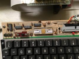
Looking at the incorrect characters problem first, it was clear that bit 4 was not being received by the character generator correctly. I was a bit worried that the SMC KR2376-17 scanner/ROM on the keyboard assembly might be at fault, since Mattis had had some trouble with his. This is a pretty cool part; a combined scanner and code translator, with an internal oscillator, rollover logic, debounce delay, and flexible interfacing:
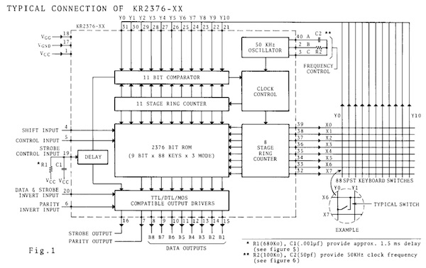
...not to mention the very cool vintage ceramic/gold packaging (see below.) Fortunately, inspection with an oscilloscope showed that the outputs from the scanner were just fine; chasing downstream, the problem was found to be just a loose pin (SS) on the keyboard cable Berg connector. With that sorted, we now have this:

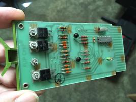
For the final issue with the top row not printing, verified that the problem followed a particular G380 solenoid driver card when swapping them around, and that with a functional G380 in the appropriate backplane slot pin 1 fires and prints correctly. Inspection of the problematic G380 revealed a failed power transistor and blown associated micro-fuse; replacement parts on order.
For the ribbon advance issue, I pulled the ribbon motors and disassembled their top-side reduction gear cases in order to gain access to the upper rotor bearings. Cleaning and lubrication of these bearings, plus a few more taps with a mallet after reassembly, achieved an improved bearing alignment. With the increased output torque, the ribbon now advances reliably.
Other minor items: Replacement vibration isolators arrived, and were installed. Threaded inserts in the fiberglass top shell that had pulled out were reattached with epoxy.
Have some more travel coming up for work, so may not be able to get back to this for a bit. Next steps will be repair of the failed solenoid driver channel, calibrations, then any debug necessary on the M7910 interface card for the PDP-11.
PDP-11/45: LA30 repair II
Sun 26 November 2017 by Fritz MuellerOkay, first thing to debug today is the ready light. This is lit by RDY LITE L, pin A16D2 (lower right of sheet M7721-0-1 in the LA30 engineering drawings). Logic probe showed this was correctly asserted low. Pulled the lamp and checked it with bench supply, and it checked fine. Verified +10 and ground at the lamp socket as well, so why isn't it lit? Turns out it is polarized, and the socket is soldered in backwards (?!). Corrected the socket, and ready light is working.
Noticed that ribbon is stalling occasionally. Ribbon tension seems to be overcoming the clutch on the take-up side. It seems tensioning drag on the inactive side is too high. Not sure what to do about this one yet; there is not much adjustable within the clutches, and the service manual only recommends replacement if they are out of spec (yeah, good luck finding one!)
Repeated the experiment with loopback jumper (A15R2 to A15C2). Turns out I had miscounted backplane pins the first time. With jumper placed correctly, I am now get a printing response to the keyboard. Not quite right, but definite progress:
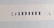
Here I had typed :;L, and then some other letters. You can see evidence of correct pins firing for the
first three characters, though either head movement or pin timing is off. Letter spacing appears more or less
correct for 80 characters per line.
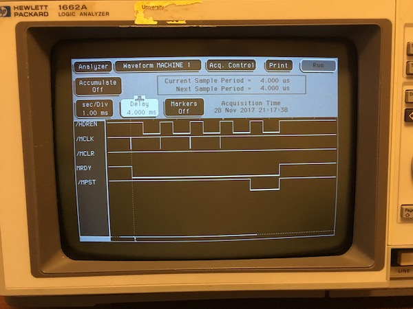
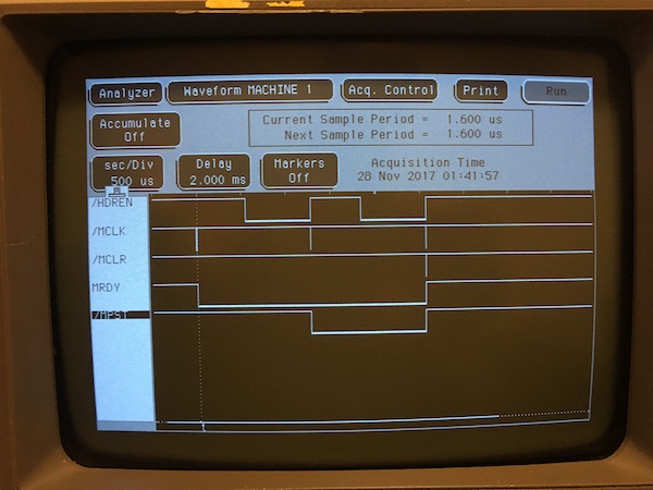
Okay, hooked up the logic analyzer, and started to take a look at the character generator clocking to see if all the the columns are being clocked out correctly. The logic analyzer shows a malfunction consistent with the print behavior: character column clocking resets after two columns rather than proceeding through all five:
This signaling is mediated by a ripple counter on the M7724 character generator card:
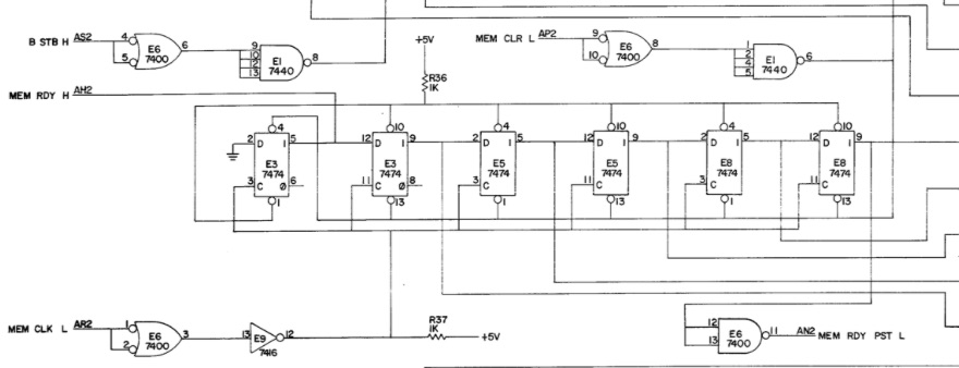
So it looks like one or more of these 7474 quad flops has failed. I note on my chargen board that these are early 70's Nat Semi parts; Mattis had a very similar issue (search "7474" on this page) on his LA30 chargen with the same parts.
All I have time for this weekend; next time I'll get the chip clip on these for a closer look, then pull and replace the baddies.
PDP-11/45: LA30 repair
Sat 25 November 2017 by Fritz MuellerOnce again its been a little while since I've had to work on PDP-11 stuff or put any updates here; the day gig has been pretty intense lately.
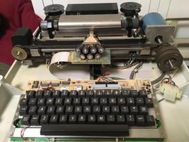
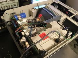
Recent efforts have been focused on restoration of an LA30 printing terminal. This was really filthy (including a mouse nest, yuck) so in addition to the usual electronics work it had to be completely disassembled for proper cleaning and lubrication.
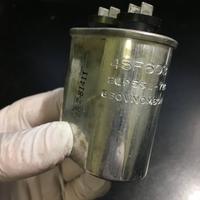
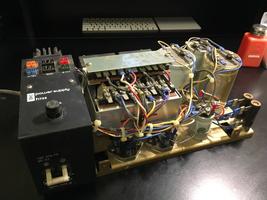
First off, the H735 power supply. This is a pretty straightforward supply, but has an oil cap in the ferro- resonant circuit that is listed as a PCB-containing component; replaced this with a modern equivalent. Also pulled and reformed all the large electrolytic caps on the bench per usual. No real trouble or surprises with this supply.
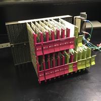
Logic assembly looks good; everything is there (mine is an LA30-P, the parallel interface version) with no obvious scorches or toast. Backplane intact and chip pin corrosion doesn't look too bad. Needed some compressed air to blow out all the dust bunnies.
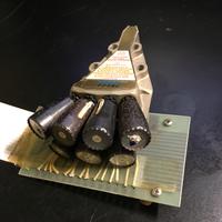
Print head also looks to be in decent shape; all of the pins fire freely when activated momentarily with a 15 VDC bench supply.
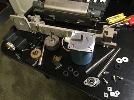
Most of the work here was involved in disassembling the top section of the terminal, including the keyboard and carriage assembles, where most of the filth had accumulated. There are a lot of parts and pieces, with castings, bearings, machined shafts, stainless and brass throughout. This thing was really well built!
The ribbon-like paper drag springs were all either torn, mangled, or cracked/cracking; I fashioned some replacements by cutting and drilling 1/2" x 3" strips of .002 steel shim stock. The rubber shock isolation mounts for the carriage assembly had also hardened and decayed. These look very close to the original; I put some on order. Replaced the bumpers on the carriage rails with some less expensive 3/8" chassis grommets. After cleaning, hit the slide rails with dry film silicone lubricant (Molykote 557) and pivot and carriage cam plates pins with a good lithium grease (Molykote BR2 Plus).
Ribbon drive motor bearings were very gummy, and one of the ribbon motors had seized. These motors are quite serviceable though; you can pull the bottom bearing cap and remove the rotor, clean the rotor shaft and bearings of old lubricants, apply fresh and reassemble. These are self-aligning bearings, so don't forget to give the assembly a few taps all around with a mallet after reassembly to shake them into true.
Consumables: compatible ribbons are still plentiful on eBay, so I ordered a few. Paper is an unusual width at 9-7/8". A few vendors on Amazon still seem to carry it, but it might be wise to lay in stock of a carton or two while it is still obtainable.
Fired it up after reassembly. No smoke (good!) and it feeps once reassuringly at power on. Ribbon motors and clutches seem to be working, and the ribbon advances. Activating the ribbon reverse switches manually reverses the ribbon movement per expectation.
If the carriage is closed with paper loaded, the print head will home left and then move right after about a second or so (per expectation; "last character visibility" feature) and ribbon advance halts. Local line feed from the front panel switch works. All of this indicates a good deal of the logic and the motor drive are already working correctly.
However: the front panel "ready" indicator does not light, and a quick loopback test (jumper A15R2 to A15C2 on the backplane) does not print any characters in response to the keyboard. Will pick up here with logic debug next time.
PDP-11/45: VT52 Keyboard Repair
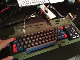
Sat 15 July 2017 by Fritz MuellerThe VT52 had a broken ESC key, and with RT-11 up and running I was motivated to dig in and fix it (you need that ESC key if you are going to run the K52 editor). Pulling the keycap and giving things a look over, the leaf contacts and the plastic plunger that activate the key looked fine. Need to get at the keyboard module itself to troubleshoot, and on a VT52 that means opening the thing all the way up and pulling the main boards. In we go...
Extracted the keyboard module, powered it from my bench supply, and used a breadboard and some jumpers to drive the key select decoders. Key closure on the back of the module was intermittent, but some flexure of the entire keyboard PCB seemed to be affecting it. Replaced/reflowed the solder on the back of the key switch and that seems to have fixed it.
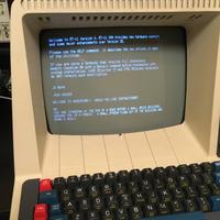
Back together, working well now. Test drove it for a while under RT-11...
PDP-11/45: Data Recovery
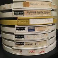
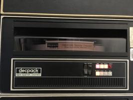
Sun 09 July 2017 by Fritz MuellerOkay, the system is working well enough now to start attempting recovery and archive of the dozen or so RK05 packs that I have on-hand. These were all obtained (along with the RK05 drives, controller and power supply) in a surplus auction downstream of Stanford's Hansen Experimental Physics Lab, sometime in the early '90s.
The packs date from the mid-70's to early-80's, and the labels indicate contents related to experiments and research projects taking place at the lab at that time. One particular pack seems associated with the Stanford Gravity Wave Project, which built early resonant mass detectors. Other packs labeled "FEL" would be related to early free-electron laser research. Many of the names on the packs are are readily found on related scientific publications from the time.
The process for dealing with these packs involves opening them up for inspection and cleaning before mounting them, with hopes of avoiding beating up or destroying the drive heads and/or media with head crashes. Much has been written about pack cleaning on the classiccmp mailing lists and in the vcfed forums, but briefly the process involves some clean-room gloves, lint-free wipes, and anhydrous isopropyl alcohol. The outside of the pack is first cleaned of dust and grime, then the packs are opened and inspected and the disk surfaces given a scrub with the wipes and alcohol. If a pack seems in good enough shape to mount, it is spun up and run in a drive with head load disabled for about a half-hour. This gets a good air-flow over the disk to blow out remaining loose particulates and also lets the disk come up to thermal equilibrium. After that the heads are loaded, with a finger standing by on the unload switch in case there are any bad noises...
I've already been dealing with two of the packs extensively during the restoration: one is an RKDP diagnostics pack, and the other was a backup pack of same. I was able to capture a complete, error-free image of the RKDP pack using PDP11GUI. This seems to be an earlier version of this disk that what is already available on bitsavers; I've sent the bits to Al Kossow, but as I understand it his project has a big backlog at the moment so it may be a while before he can consider my submission. In the meantime, for those interested, the disk image is available here.
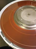
The RKDP backup disk was used as a test pack during the RK11/RK05 restoration work, and thus was overwritten by the RK05 diagnostic read/write tests. It now contains a bootable RT-11 image, written via PDP11GUI. Mixed results on the other packs so far: some have had severe head crashes (see pic below) or are otherwise damaged to the point that I am hesitant to mount them. Some have been mysteriously unreadable. It looks like I can expect about 50% recovery. Results so far are tabulated here. I hope to be able to make other recovered images available soon, but since they contain original research materials I am trying to contact the authors for permission first.
| Serial # | Label | OS | Notes |
|---|---|---|---|
| ZO 50511 | MAINDEC-11-DZZAA-J-HB 9/21/74 M XXDP RKDP RK11 DIAGNOSTIC PACKAGE |
DZQUD-A RKDP-RK11 MONITOR | [1974] MAINDEC diagnostics for PDP-11/40/45 CPU/MMU/FPU, MS11, DL11, DR11, RK11, LC11/LA30, KW11-L/P. Full recovery. |
| B1-75814 | RKDB Backup | unknown | [unknown] Presumed to be backup of ZO 50511; used as test disk and overwritten. |
| B1-28320 | Gravitational Radiation Experiment Boughn, Hollenhorst, Paik, Sears, Taber MSA |
DOS/BATCH V09-20 | [1976-77] Fortran and MACRO-11 codes, mostly calculations relating to resonant mass detector design. Full recovery. |
| AD-21279 | BLAZQUEZ RT-11 AUG 83 | RT-11FB (S) V04.00L | [1983] Fortran and MACRO-11 codes relating to image processing and display. Device driver code for DeAnza Systems ID-2000 display and Calcomp plotter. Names: Ken Dinwiddie (DeAnza codes), Art Vetter (Calcomp codes). Full recovery. |
| BAK 9069 A | W. COLSON | DOS/BATCH V9-20C | [1977-78] Full recovery. |
| AE 61745 | FEL L.ELIAS | DOS/BATCH V9-20C | [1974-78] Head crash on read (ouch!) Partial recovery. Unrecovered data looks to be mostly OS files; may be patchable. |
| ZO 50399 | TRANSPORT + DATA 1/18/80 |
DOS/BATCH V9-20C | [1980-83] Minor corrosion spot. Partial recovery. Data files and Fortran programs. |
| E172140 | M. O'Halloran Ray Tracing R. RAND BBU PROGRAMS |
TBD | [TBD] |
| B1-45441 | RT 11 | TBD | [TBD] Minor head crashes on media. |
| B1-24056 | RDAS | DOS/BATCH V9-20C | [1970-78, 1983] Minor head crashes on media. Partial recovery. FEL related Fortran codes. |
| AE 20116 | DEACON FEL | unknown | [unknown] Many corrosion spots on media; did not mount. |
| 19177 | Transport DOS/BATCH-9 V 20C | unknown | [unknown] Major head crash on media; did not mount. |
| B1-44898 | RDAS9 - V20C | unknown | [unknown] Medium head crashes on media; did not mount. |
PDP-11/45: First RT-11 Boot From Disk!
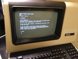
Thu 06 July 2017 by Fritz MuellerNot much technical in this post, except the big ticket news: after all the recent repairs and generating a fresh RT-11 pack RT-11 BOOTS FROM DISK!
It's been a very long road getting here, but the machine finally has a working, full-featured, operating system, capable of supporting self-hosted program development. Spent a few enjoyable hours editing, assembling, linking, and debugging some small MACRO-11 hacks directly on the machine, using the native RT-11 tools. This is probably a 40 year high-water-mark of functionality for these particular bits of hardware. Very satisfying!
Next up will be to clean and inspect the dozen or so RK05 packs that I have on hand, and retrieve and archive whatever content I can. That should let me clear off a few packs to create some space to experiment with some additional operating systems, including 6th Edition Unix.
PDP-11/45: M9301 Troubles
Tue 04 July 2017 by Fritz MuellerAfter a lot of recent progress with the RK11, suffered a setback: after trying once again to image a fresh RT-11 pack, the machine began to behave erratically at boot. Sometimes the boot monitor would run fine, sometimes it would run for a while and then take a machine exception or vector off to bad address, and sometimes the machine would fail to boot at all, immediately taking exceptions of various sorts. Getting so close, but then lost a lot of ground; I guess that's sort of the way it is going to be with a machine that is this old...
So, back to the top without a working boot monitor. Microcode sequencing and seemed to be working fine -- exam/deposit/step working reliably from the front panel. Checked execution of the first few instructions of the boot ROM in detail, a branch and some single operand instructions, and they seemed to execute correctly.
Assuming some sort of new failure in the CPU, I prepared to instrument the Unibus with the HP logic analyzer; it seemed that way I could trigger on machine exceptions then look back over the captured address traces for a pattern. To make sense of those, I'd need a listing of the boot ROM in hand. Noel Chiappa has a dump for this and a partial disassembly on his site here, but is it the same as mine? Better check...
Started to run through Noel's listing and compare to the ROM contents on my machine via front panel exam. Sure enough, there seemed to be some words different in a few places. Maybe the CPU is fine, and the ROM card is failing? Swapped out the M9301 for a simpler M792 diode matrix boot ROM, and sure enough -- was able to boot straight away off my RKDP pack, and from there reliably beat up the CPU with diagnostics. So, great news: just a failing M9301!
Alright, so now I want to capture a dump of the M9301 so I can systematically compare with Noel's listing to see if there's a pattern in failed/flaky bits to help guide my repair. For this I need a memory dump utility that I can toggle in from the front panel. Came up with this:
1 2 3 4 5 6 7 8 9 10 11 12 13 14 15 16 17 18 19 20 21 22 23 24 25 26 27 28 29 30 31 32 33 34 35 36 | 001000 012705 START: MOV #177564,R5 ;CONSOLE XCSR
177564
001004 012700 L0: MOV #177570,R0 ;SWITCH REGISTER
177570
001010 000000 HALT
001012 011004 MOV @R0,R4 ;READ ADDR FROM SWITCHES
001014 000000 HALT
001016 011003 MOV @R0,R3 ;READ COUNT FROM SWITCHES
001020 012401 L1: MOV (R4)+,R1 ;GET NEXT WORD TO DUMP
001022 012702 MOV #6,R2 ;SIX DIGITS TO PRINT
000006
001026 005000 CLR R0 ;R0 GETS MSB R1
001030 073027 ASHC #1,R0
000001
001034 062700 L2: ADD #60,R0 ;MAKE INTO ASCII DIGIT
000060
001040 010065 MOV R0,2(R5) ;OUTPUT
000002
001044 105715 TSTB (R5)
001046 100376 BPL .-2
001050 005000 CLR R0 ;R0 GETS 3 MSB R1
001052 073027 ASHC #3,R0
000003
001056 077212 SOB R2,L2 ;LOOP DIGITS
001060 012765 MOV #15,2(R5) ;OUTPUT '\R'
000015
000002
001066 105715 TSTB (R5)
001070 100376 BPL .-2
001072 012765 MOV #12,2(R5) ;OUTPUT '\N'
000012
000002
001100 105715 TSTB (R5)
001102 100376 BPL .-2
001104 077333 SOB R3,L1 ;LOOP WORDS
001106 000736 BR L0 ;START OVER
|
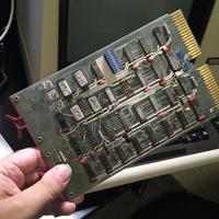
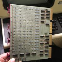
Executed this a few times and got slightly different results, then things settled into a pattern where the lowest nybble of every word was consistently zeroed but everything else was fine. Smoking gun pointing to a single PROM on the M9301. Pulled and reseated that chip, and did the same for the other three while I was at it, and ... everything 100% after that. Wow, really should have just tried that first...
Well, at least I'm up and running again! The memory dump program might come in useful again at some other time, and as a byproduct after I fixed my M9301 I got 100% agreement with Noel's listing. So I think that listing can be considered authoritative now; good enough to generate replacement PROMs should anybody ever need to do so.
PDP-11/45: RK11 VII
Sun 25 June 2017 by Fritz MuellerOkay, back from travel and picked up the thread on the RK11 interrupt problem this weekend. Put the KM11 in the first slot on the RK11 which allows to monitor interrupt request. An interrupt can be very easily generated from the front panel by writing bit 6 (Interrupt on Done Enable) on in the RKCS register at 777404. Did this, and noticed that interrupt request logic on the RK11 went active, but never cleared.
Checked bus request and grant continuity all the way through to the CPU backplane and back and that looked fine (the RK11 in its default configuration uses BR5).
Chased bus request with a logic probe all the way to the CPU backplane, and it was being asserted correctly. Looking at BG5, however, I noticed it was always asserted, even if BR5 was inactive. Disconnected all peripherals and terminated the Unibus directly on the CPU backplane, and this was still the case. So there was problem with BG5 in the CPU itself.
Threw the CPU UBC card out on extenders, and took a look at BG5 logic with a logic probe. The 8881 driver for this signal (E42 on sheet UBCD of the engineering drawings) had failed -- pins 8 and 9 were high, but pin 10, BG5, was not being driven low. Pulled this chip, put in a socket and a replacement, and the BG was then working properly. That's three repairs total to this poor old UBC card so far! Was able to then verify from the front panel that the processor fielded interrupt 220 in response to setting the IDE bit in RKCS. Progress!
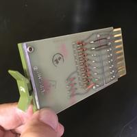
Back to the MAINDEC ZRKK -- interrupt test now passes, and the diagnostic continues. BUT... error output now on test octal 57, which is working out the "hardware pole" feature of the controller. Thought this might be due to the RK11 being configured for two RK05 drives, but I have restored/connected only the first. Rejumpered the G740 flipchip for a single drive, but this didn't seem to help. Hmmm, will need to read the diagnostic source to see what it is trying to do...
PDP-11/45: RK11 VI - "Pole" and Interrupt Issues
Thu 08 June 2017 by Fritz MuellerReplaced the failed 7401 in the RKDA to RKDB data path, and verified that the RKDB stuck bit 11 problem was fixed. Ran the system for another couple hours to rewrite a fresh RT-11 pack, then another problem developed: read operations would successfully obtain the bus, but would never complete.
Some investigation with a KM11 on the RK11 controller showed that POLE was now incorrectly asserted continuously (did they mean "poll"?). Tracked this down to a failed 7420 (E1 on the M141 at A26, sheet RK11-C-12). Replaced, and reads were working again. I guess with a machine this age there is going to be a lot of this sort of thing where marginal parts give up after a few hours of use. Hopefully after some prolonged operation things will settle down a little bit...
In any case, still unable to boot any of my RT-11 packs. I Decided to step back and run MAINDEC diagnostic ZRKK. This is the RK11 dynamic diagnostic that destructively modifies a pack, and I had not previously run it -- I had just optimistically jumped to trying to boot existing packs after the drive restore and calibration. The diagnostic ran successfully for a while, through various format and read and write tests over the whole pack (encouraging!), then hung up consistently on test 35 (octal), which tests whether the RK11 interrupts the processor correctly when IDE is set.
So it could be the case that my RT-11 boots hang up when they first start trying to make use of interrupts. Verified that I can run MAINDEC ZKWA, which tests interrupts from the KW11-L line clock, so interrupt fielding in the CPU looks good.
Re-ran MAINDEC ZRKK, and noted that the CPU is waiting in micro-state BRK.00 (154) on page FLOWS 12 of the engineering drawings. This state has a wait for Unibus INTR to be asserted, so it looks like a problem with interrupt signaling on the RK11 side.
I have a bit of travel coming up, so I probably won't get back to this for a week or two. But the next sensible step I think will be to work with a logic analyzer on the backplane of the RK11, slot A6 where the M7820 interrupt control flipchip goes, and see what is/isn't happening with the interrupt signaling on that end. I suspect there will probably be a failed IC on the M7820.
PDP-11/45: RK11 V - Checksum issues
Sun 21 May 2017 by Fritz MuellerDecided to use the disk utilities provided in PDP11GUI to write a fresh RT-11 pack. PDP11GUI successfully assembled and downloaded a driver, then took a little under 2 hours to download the pack image over the console serial line and write the pack without indicating any errors.
The resulting pack fared no better at boot than any of my existing legacy packs, however. I attempted to verify the pack via PDP11GUI, and noticed that the controller was indicating checksum errors for every sector on cylinders 64-127 and 192-202 (that is, whenever bit 11 of the RKDA was set). Tried this on several other packs, including the RKDP pack which had previously booted, and found that these errors were returned for these cylinders on all packs, so definitely a controller or drive issue, and not specific to any particular pack.
Verified that bit 11 of the RKDA could be read and written normally, and that when so addressed the RK05 drive would mechanically seek to the correct cylinders. Programmed some format-mode reads (these just return sector headers) manually via the front panel, and verified that the sector headers were being returned correctly from disk for the affected cylinders.
Tried a few flipchip swaps to see if the affected bit would move: B18 and B19 (adder; sheet RK11-C-14; no change), A21 and B21 (RKDB; sheet RK11-C-10; no change).
Programmed some all-mode reads (these return preamble, header, data, and postamble) manually via the front panel. These showed that during reads of affected cylinders, bit 11 was stuck always on. When reading unaffected cylinders, bit 11 turned on and off normally. So it seemed bit 11 was "leaking" from RKDA to RKDB.
Seeing this, tried a few more swaps: A15 and B15 (internal bus, sheet RK11-C-20, no change), A23 and B23 (RKDB data path; sheet RK11-C-21; bingo!). Stuck bit went away on this last swap. So it looks like a failed 7401, E2 on the M149 in slot A23. Pulled, socketed, and put some 7401 on order at Jameco where I can pick them up tomorrow on my way in to work. Getting closer!