PDP-11/45: RK11 II
Mon 20 February 2017 by Fritz MuellerOkay, moving on with the RK11-C debug, the following bit of test code is modeled after that part of the ZRKJE0 diagnotic that is trapping out:
1 2 3 4 5 6 7 8 9 10 11 12 13 14 15 16 17 18 19 20 21 22 23 24 | 177404 RKCS=177404
000000 .ASECT
001000 .=1000
001000 012706 000770 START: MOV #770,SP ;INIT STACK POINTER
001004 005000 CLR R0 ;INIT TRAP BASE
001006 012701 000002 MOV #2,R1 ;INIT TRAP DEST
001012 010120 L1: MOV R1,(R0)+ ;STORE TRAP DEST
001014 005020 CLR (R0)+ ;AND STORE HALT AT TRAP DEST
001016 062701 000004 ADD #4,R1 ;UPDATE TRAP DEST
001022 020600 CMP SP,R0 ;ALL TRAPS INITD?
001024 001372 BNE L1 ;IF NOT, KEEP GOING
001026 005002 CLR R2 ;INIT MAIN ITERATION COUNT
001030 005202 L2: INC R2 ;INC MAIN ITERATION COUNT
001032 010237 177570 MOV R2,@#177570 ;UPDATE DISPLAY REG
001036 012700 177404 MOV #RKCS,R0 ;GET RKCS ADDRESS
001042 012710 007560 MOV #7560,@R0 ;SET RESET CTRLR CMD
001046 005210 INC @R0 ;SET GO BIT
001050 005005 CLR R5 ;INIT CHECK COUNT
001052 105710 L3: TSTB @R0 ;CHECK DONE BIT
001054 100765 BMI L2 ;IF SET, NEXT MAIN LOOP
001056 005205 INC R5 ;OTHERWISE INC CHECK COUNT
001060 001374 BNE L3 ;IF NOT EXPIRED GO CHECK AGAIN
001062 000000 HALT ;OTHERWISE, HALT HERE
001000 .END START
|
Running this code, the error is easily reproduced -- the machine traps on a bus timeout and halts after anywhere from a few dozen to a few hundred iterations. Put the logic analyzer on MSYN and SSYN at the back M105 address decode module on the RK11-C backplane and set up a trigger for long bus cycles, but surprisingly this was not triggering even though the processor was taking a trap 4. Verified that the trigger itself was working fine by accessing a non-existent memory location from the front panel. Hmmm...
Next step then was to move back to the CPU, and throw the UBC card out on extenders to get more visibility into the trap. A further surprise here -- the problem went away when the UBC was on the extender! I was able to run the test code above for hundreds of thousands of iterations without timeouts, and the original ZRKJE0 diagnostic ran for over half an hour this way.
Took the UBC back off the extender, and the problem re-occurred, so apparently not just a bad seat. Hooked the logic analyzer up to BUS A MSYN L, BUS A SSYN L, and UBCB TIMEOUT (1) H on the 11/45 backplane. With this, I was able to capture lots of traces of the failure mode, which looks like this:
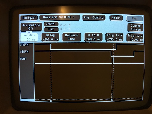
Here a glitch on the timeout signal is clearly visible, even though the MSYN/SSYN interval is well under the bus timeout. The interesting thing is that bus cycles that result in a glitch all have a MSYN/SSYN interval of 568 nanosceconds, to within a nanosecond. Cycles with a slightly different interval do not timeout. This jibes with what I saw with the card extender also. As a further verification, replaced the M920 bus jumper I'd been using with a 2-foot BC11, and the problem disappeared again.
At this point, Don over on the VCFED forum pointed out that the M920 I had been using was discontinued early on due to negative effects on bus signal integrity, and was replaced with the M9202 (which itself contains 2 feet of BC11). The issue with the M920 is apprently that it provides so little separation that the connected loads appear to the bus overall as a single lumped load. The M9202 separates the loads on the bus to smear out reflections and ringing and avoid false triggers. I have tracked down an M9202 on eBay, and have also put an inexpensive digital storage scope on order so I can start to investigate signal integrity issues like this that are not apparent on a logic analyzer.
PDP-11/45: RK11
Sun 29 January 2017 by Fritz MuellerFinished up the cleanup and rebuild of the H720E for the RK11-C controller: reformed the big electrolytics over a couple of days, and swapped out the tantalum filters on the regulator board (one of which had started to leak) for some replacements. Tantalums of the correct form and value are crazy expensive, and since these caps (C11-C17, C23) are banked resevoirs on the regulated rails their exact values are not critical. Went with some aluminum electrolytics instead that worked out to a little more aggregate capacity on each bank.
My H720E is missing its top cover plate, so there was about 40 years worth of accumulated dust in there -- a lot to clean up! I'm not sure if the cover was customarily left off to facilitate cooling of the regulator board, or if it is just genuinely missing. Will see if the forums/lists have any wisdom here. Should not be hard to fab a replacement if it is really supposed to be there.
Routed the inter-cabinet power control wiring, racked the RK11, and cabled everything up. This included moving the M9301 bootstrap terminator over to slot 0, then rummaging through a box of BC11 bus cables for one that was both long enough and in decent enough shape to connect the CPU and the RK11. Some of these bus cables had period-correct labeling (see picture below :-)) Got a good tip off the cctalk mailing list (thanks, Jerry!) to drape the BC11 with a service loop from the top-rear of the CPU rack, thus avoiding any entanglement with the rack slides while moving the CPU cabinet in and out.
A 2000pF cap that was flown over the RK11 backplane (+5V to DR BUS DC LO L) had broken free of its pin connectors; jury-rigged this with some arduino jumpers I had lying around, until I can track down some appropriate replacement connectors.
Good news is that after this the machine still booted the M9301 bootstrap, and was still able to run and pass diagnostics loaded via PDP11GUI. So, Unibus still working with the BC11 cable in place and termination out at the RK11.
Started in with diagnostic ZRKJE0.BIC, which is the controller-only static test. This indicated:
REGISTER NOT CLEARED
  PC   REGADD    RECVD
002560  177416  040000
This is the RKDB register, implemented by two M203 R/S flip-flop modules in slots A21 and B21 (see sheet RK11-C-10 in the RK11-C engineering drawings). Swapped these, and the stuck bit moved to the other half of of the register, so looks like failed gate. Pulled, socketed, replaced, and diagnostic no longer reports any stuck bits. Next diagnostic fail is:
UNEXPECTED TIME OUT AT PC=004300
This is test #21 of the diagnostic, testing controller reset. Will need to do some reading up on the design of the controller and the diagnostic source to understand how to troubleshoot it further. All for now!


PDP-11/45: Diagnostics XIV - CPU, MMU, FPU Complete!
Mon 16 January 2017 by Fritz MuellerOkay, after socketing in the replacement 74H10 and reseating a few boards, the output from the floating point diagnostic now looks correct:
................ ................ ................ ................ .........11..... .........11..... .........11..... .........11..... ................ ................ ................ ................ ..........11.... ..........11.... ..........11.... ..........11.... ................ ................ ................ ................ ...........11... ...........11... ...........11... ...........11... ................ ................ ................ ................ ............11.. ............11.. ............11.. ............11.. ................ ................ ................ ................ .............11. .............11. .............11. .............11. ................ ................ ................ ................ ..............11 ..............11 ..............11 ..............11 ................ ................ ................ ................ ...............1 1..............1 1..............1 1..............1 .......111...... ................ ................ ................ ................ 11.............. 11.............. 11.............. .......1111..... ................ ................ ................ ................ .11............. .11............. .11............. ..........11.... ................ ................ ................ ................ ..11............ ..11............ ..11............ ...........11... ................ ................ ................ ................ ...11........... ...11........... ...11........... ............11.. ................ ................ ................ ................ ....11.......... ....11.......... ....11.......... .............11. ................ ................ ................ ................ .....11......... .....11......... .....11......... ..............11 ................ ................ ................ ................ ......11........ ......11........ ......11........ ...............1 1............... ................ ................ ................ .......11....... .......11....... .......11....... ................ 11.............. ................ ................ ................ ........11...... ........11...... ........11...... ................ .11............. ................ ................ ................ .........11..... .........11..... .........11..... ................ ..11............ ................ ................ ................ ..........11.... ..........11.... ..........11.... ................ ...11........... ................ ................ ................ ...........11... ...........11... ...........11... ................ ....11.......... ................ ................ ................ ............11.. ............11.. ............11.. ................ .....11......... ................ ................ ................ .............11. .............11. .............11. ................ ......11........ ................ ................ ................ ..............11 ..............11 ..............11 ................ .......11....... ................ ................ ................ ...............1 1..............1 1..............1 .......111...... ........11...... ................ ................ ................ ................ 11.............. 11.............. .......1111..... .........11..... ................ ................ ................ ................ .11............. .11............. ..........11.... ..........11.... ................ ................ ................ ................ ..11............ ..11............ ...........11... ...........11... ................ ................ ................ ................ ...11........... ...11........... ............11.. ............11.. ................ ................ ................ ................ ....11.......... ....11.......... .............11. .............11. ................ ................ ................ ................ .....11......... .....11......... ..............11 ..............11 ................ ................ ................ ................ ......11........ ......11........ ...............1 1..............1 1............... ................ ................ ................ .......11....... .......11....... ................ 11.............. 11.............. ................ ................ ................ ........11...... ........11...... ................ .11............. .11............. ................ ................ ................ .........11..... .........11..... ................ ..11............ ..11............ ................ ................ ................ ..........11.... ..........11.... ................ ...11........... ...11........... ................ ................ ................ ...........11... ...........11... ................ ....11.......... ....11.......... ................ ................ ................ ............11.. ............11.. ................ .....11......... .....11......... ................ ................ ................ .............11. .............11. ................ ......11........ ......11........ ................ ................ ................ ..............11 ..............11 ................ .......11....... .......11....... ................ ................ ................ ...............1 1..............1 .......111...... ........11...... ........11...... ................ ................ ................ ................ 11.............. .......1111..... .........11..... .........11..... ................ ................ ................ ................ .11............. ..........11.... ..........11.... ..........11.... ................ ................ ................ ................ ..11............ ...........11... ...........11... ...........11... ................ ................ ................ ................ ...11........... ............11.. ............11.. ............11.. ................ ................ ................ ................ ....11.......... .............11. .............11. .............11. ................ ................ ................ ................ .....11......... ..............11 ..............11 ..............11 ................ ................ ................ ................ ......11........ ...............1 1..............1 1..............1 1............... ................ ................ ................ .......11....... ................ 11.............. 11.............. 11.............. ................ ................ ................ ........11...... ................ .11............. .11............. .11............. ................ ................ ................ .........11..... ................ ..11............ ..11............ ..11............ ................ ................ ................ ..........11.... ................ ...11........... ...11........... ...11........... ................ ................ ................ ...........11... ................ ....11.......... ....11.......... ....11.......... ................ ................ ................ ............11.. ................ .....11......... .....11......... .....11......... ................ ................ ................ .............11. ................ ......11........ ......11........ ......11........ ................ ................ ................ ..............11 ................ .......11....... .......11....... .......11....... ................ ................ ................ ...............1 .......111...... ........11...... ........11...... ........11...... ................ ................ ................ ................ .......1111..... .........11..... .........11..... .........11..... ................ ................ ................ ................ .........11..... .........11..... .........11..... .........11..... ................ ................ ................ ................
With this fix, the machine is now reliably passing the complete suite of CPU, MMU, and FPU diagnostics -- a real milestone! I also loaded paper tape BASIC via PDP11GUI, swapped the console over to my VT100, and played around for a little bit. Working well, and gratifying to see the machine actually running some software other than diagnostics.
So, now, on to the RK11/RK05 storage subsystem for real. I retrieved the rest of the cabinetry, cleaned and reassembled it, and inspected and cleaned the cabinet-top 860 power controller in the second cabinet. This had the usual dead neon indicator and a blown fuse, but was otherwise in good shape. At first I was puzzled by the relay in the 860 not engaging, but after looking at the schematic is was clear that a jumper plug on J4 connecting pins 1 and 2 was required. I recalled seeing one such banging around loose in my spare parts box -- so that's where that came from! Cleaned up the cabinet-top fan in the second cabinet as well.
I have been running the machine off a GFCI quad box behind my washer/dryer, but at this point there is enough leakage through filter caps in the various power supplies that the GFCI has started to trip from time to time. Took a pause to rewire the box -- left two of the outlets GFCI protected for the washer/dryer, and rewired two as non-protected for use with the PDP-11.


PDP-11/45: Diagnostics XIII - FP11 FPU, cont.
Thu 24 November 2016 by Fritz MuellerHave been looking into the FP11 MOD problem in spare moments of the past few weeks, but haven't written up an account of the progress, so this will be a bit of a catch-up article.
Having now studied the design of this thing in more depth, there are a few things I find interesting:
-
The inner loops of the multiplication, division, and floating-point normalization algorithms on the FP11 are not implemented in microcode, but rather as "hardware subroutines". Microcode does all the setup of the various internal registers and counters, then pauses while the hardware runs the inner loop, then picks up again to mediate rounding, masking, exceptions, etc. afterward.
-
The multiplication implementation uses an interesting algorithm called "skipping over ones and zeros", described in section 5.3.1 of the FP11 maintenance manual. This reduces the number of time-consuming additions needed on average. It works along the lines of a familiar mental shortcut: suppose you had to multiply some number X by 999. Rather than multiply X by 9 three times and shift and add them all up, you would probably just take X * 1,000 and subtract off X * 1. The key observation is that you can do this for any contiguous string of 9s in the multiplier: subtract the multiplicand from the partial product at the place value where the string begins, then add the multiplicand at one past place value where the string ends. The FP11 implements the binary equivalent of this with a small state machine (comprised of flip-flops MR1, MR0, and STRG1) which identifies strings of contiguous 1s and invokes ALU subtractions and additions on the boundaries as the multiplier is shifted through.
-
Debugging techniques: a KM11 in single-clock-transition mode may be used to step within the hardware subroutines, as they are driven off the main FP11 clock. It can be a lot of switch presses to step through an entire multiply (120 or so clock transitions at least for a double-precision multiply, and typically more because each necessary intermediate add/subtract adds eight clock transitions!) and this gets to be pretty tedious and error-prone. A logic analyzer is very useful here to capture a visualization of an entire multiplication at one go, and enable counting off clock transitions needed to get to something you'd like to take a closer look at with a logic probe. Alternatively, if your FP11 is working well enough to run maintenance instructions, there are software techniques that can prematurely terminate the hardware subroutines and also give some useful visibility into the intermediate states.
I opted to try out the software techniques to see if I could get more information on the (mis)behavior in my FP11 order to focus my hardware troubleshooting. The following program came in handy. This is based off some example code in the FP11 maintenance manual, though I elaborated it slightly with a binary printout routine:
1 2 3 4 5 6 7 8 9 10 11 12 13 14 15 16 17 18 19 20 21 22 23 24 25 26 27 28 29 30 31 32 33 34 35 36 37 38 39 40 41 42 43 44 45 46 47 48 49 50 51 52 53 54 55 56 57 58 59 60 61 62 63 64 65 66 67 68 69 70 71 72 73 74 75 76 77 78 79 80 81 82 83 84 85 | 000000 AC0=%0
000001 AC1=%1
000002 AC2=%2
177560 SERIAL=177560
170006 MRS=170006
000000 .ASECT
001000 .=1000
001000 170127 040220 START: LDFPS #40220 ;DISABLE INTS, SET DBL AND MAINT MODE
001004 172667 000316 LDD MLYR,AC2 ;LOAD MULTIPLIER IN AC2
001010 012703 000230 MOV #230,R3 ;R3 GETS OCTAL 230 (FRAC MUL MICROSTATE)
001014 170003 LDUB ;LOAD R3 TO MBR
001016 012702 177564 MOV #SERIAL+4,R2 ;SERIAL XMIT BASE TO R2
001022 012762 000015 000002 MOV #15,2(R2) ;OUTPUT '\R'
001030 105712 TSTB (R2) ;CHECK XMIT CLEAR
001032 100376 BPL .-2 ;LOOP UNTIL SO
001034 012762 000012 000002 MOV #12,2(R2) ;OUTPUT '\N'
001042 105712 TSTB (R2) ;CHECK XMIT CLEAR
001044 100376 BPL .-2 ;LOOP UNTIL SO
001046 005004 CLR R4 ;R4 HOLDS SC VALUE
001050 005204 NXTMUL: INC R4 ;INCREMENT SC
001052 170004 LDSC ;LOAD 1S COMPLEMENT OF R4 INTO SC
001054 012705 001356 LSTMUL: MOV #QR+10,R5 ;SET R5 PAST END OF STORAGE TABLE
001060 172567 000232 LDD MCND,AC1 ;LOAD MULTIPLICAND INTO AC1
001064 171102 MULD AC2,AC1 ;DO PARTIAL MULTIPLY
001066 170007 STQ0 ;TRANSFER QR TO AC0
001070 174045 STD AC0,-(R5) ;STORE QR IN TABLE
001072 042715 177600 BIC #177600,(R5) ;CLEAR OFF SIGN AND EXPONENT
001076 170005 STA0 ;TRANSFER AR TO AC0
001100 174045 STD AC0,-(R5) ;STORE AR IN TABLE
001102 042715 177600 BIC #177600,(R5) ;CLEAR OFF SIGN AND EXPONENT
001106 170006 MRS ;SHIFT AR AND QR RIGHT ONE PLACE
001110 170006 MRS ;SHIFT AR AND QR RIGHT ONE PLACE
001112 170007 STQ0 ;TRANSFER QR TO AC0
001114 174067 000236 STD AC0,TEMP ;STORE QR IN TEMP
001120 016703 000232 MOV TEMP,R3 ;FETCH MSW OF QR TO R3
001124 042703 177600 BIC #177600,R3 ;CLEAR OFF SIGN AND EXPONENT
001130 006303 ASL R3 ;SHIFT MSBS OF QR ONE PLACE LEFT
001132 006303 ASL R3 ;SHIFT MSBS OF QR ONE PLACE LEFT
001134 050365 000010 BIS R3,10(R5) ;SET QR59 AND QR58 IN TABLE
001140 170005 STA0 ;TRANSFER AR TO AC0
001142 174067 000210 STD AC0,TEMP ;STORE AR IN TEMP
001146 016703 000204 MOV TEMP,R3 ;FETCH MSW OF AR TO R3
001152 042703 177600 BIC #177600,R3 ;CLEAR OFF SIGN AND EXPONENT
001156 006303 ASL R3 ;SHIFT MSBS OF AR ONE PLACE LEFT
001160 006303 ASL R3 ;SHIFT MSBS OF AR ONE PLACE LEFT
001162 050315 BIS R3,(R5) ;SET AR59 AND AR58 IN TABLE
001164 012705 001336 MOV #AR,R5 ;GET ADDRESS OF FIRST QUAD FOR PRINTING
001170 012700 000010 MOV #10,R0 ;R0 COUNTS 8 WORDS IN TWO QUADS
001174 012503 LWORD: MOV (R5)+,R3 ;FETCH NEXT WORD OF QUAD
001176 012701 000020 MOV #20,R1 ;R1 COUNTS 16 BITS IN WORD
001202 006103 LBIT: ROL R3 ;ROTATE, HIGH BIT GOES TO CARRY
001204 103405 BCS LBIT1 ;SKIP AHEAD IF CARRY SET
001206 012762 000056 000002 MOV #56,2(R2) ;OTHERWISE OUTPUT '.'
001214 000167 000006 JMP LBIT2 ;AND SKIP AHEAD
001220 012762 000061 000002 LBIT1: MOV #61,2(R2) ;OUTPUT '1'
001226 105712 LBIT2: TSTB (R2) ;CHECK XMIT CLEAR
001230 100376 BPL .-2 ;LOOP UNTIL SO
001232 077115 SOB R1,LBIT ;LOOP OVER BITS IN WORD
001234 012762 000040 000002 MOV #40,2(R2) ;OUTPUT ' ' TO SEPARATE WORDS
001242 105712 TSTB (R2) ;CHECK XMIT CLEAR
001244 100376 BPL .-2 ;LOOP UNTIL SO
001246 077026 SOB R0,LWORD ;LOOP OVER WORDS IN QUAD
001250 012762 000015 000002 MOV #15,2(R2) ;OUTPUT '\R'
001256 105712 TSTB (R2) ;CHECK XMIT CLEAR
001260 100376 BPL .-2 ;LOOP UNTIL SO
001262 012762 000012 000002 MOV #12,2(R2) ;OUTPUT '\N'
001270 105712 TSTB (R2) ;CHECK XMIT CLEAR
001272 100376 BPL .-2 ;LOOP UNTIL SO
001274 020427 000071 CMP R4,#71 ;CHECK PASSES AGAINST 57
001300 100663 BMI NXTMUL ;LESS: DO NEXT PASS
001302 001402 BEQ LSTPAS ;EQUAL: DO LAST PASS
001304 000167 171470 JMP 173000 ;GREATER: RETURN TO M9301 MONITOR
001310 005204 LSTPAS: INC R4 ;INDICATE 58TH PASS
001312 000167 177536 JMP LSTMUL ;DO LAST PASS WITHOUT LOADING SC
001316 040200 000000 000000 MCND: .WORD 040200, 000000, 000000, 000000
001324 000000
001326 040300 000300 000300 MLYR: .WORD 040300, 000300, 000300, 000300
001334 000300
001336 000000 000000 000000 AR: .FLT4 0
001344 000000
001346 000000 000000 000000 QR: .FLT4 0
001354 000000
001356 000000 000000 000000 TEMP: .FLT4 0
001364 000000
001000 .END START
|
The idea here is to use the LDUB (load micro-break) and LDSC (load step-counter) maintenance instructions to cause a multiplication to halt partway through. STA0 and STQ0 (store AR, store QR) instructions, in conjunction with the MRS (maintenance right shift) instruction, allow retrieval of the internal fraction registers which are then printed out to the serial console. This is done repetitively, stopping each time one step further on, so the progression of the internal states of AR and QR over the course of the entire multiply may be observed.
A quick aside here on tooling: since I don't currently have any storage or an OS running on my PDP-11, I load and execute diagnostics with PDP11GUI to an M9301 boot monitor over a serial connection. This requires program binaries in LDA (absolute loader) format. For non-trivial MACRO-11 programs I have found it most convenient to use the actual vintage toolchain under RT-11 in the simh simulator, because the assembler and linker provided with PDP11GUI have some limitations. I copy files in and out via the simulated paper tape reader/punch. This is also how I produce the MACRO-11 listings seen on this blog.
Okay, back to the program above, running this on my machine very clearly illustrates the malfunction. Here's what the output looks like:
................ ................ ................ ................ .........11..... .........11..... .........11..... .........11..... ................ ................ ................ ................ ..........11.... ..........11.... ..........11.... ..........11.... ................ ................ ................ ................ ...........11... ...........11... ...........11... ...........11... ................ ................ ................ ................ ............11.. ............11.. ............11.. ............11.. ................ ................ ................ ................ .............11. .............11. .............11. .............11. ................ ................ ................ ................ ..............11 ..............11 ..............11 ..............11 ................ ................ ................ ................ ...............1 1..............1 1..............1 1..............1 .......11.111111 1111111111111111 1111111111111111 1111111111111111 ................ 11.............. 11.............. 11.............. .......111.11111 1111111111111111 1111111111111111 1111111111111111 ................ .11............. .11............. .11............. ..........1.1111 1111111111111111 1111111111111111 1111111111111111 ................ ..11............ ..11............ ..11............ ...........1.111 1111111111111111 1111111111111111 1111111111111111 ................ ...11........... ...11........... ...11........... ............1.11 1111111111111111 1111111111111111 1111111111111111 ................ ....11.......... ....11.......... ....11.......... .............1.1 1111111111111111 1111111111111111 1111111111111111 ................ .....11......... .....11......... .....11......... ..............1. 1111111111111111 1111111111111111 1111111111111111 ................ ......11........ ......11........ ......11........ ...............1 .111111111111111 1111111111111111 1111111111111111 ................ .......11....... .......11....... .......11....... ................ 1.11111111111111 1111111111111111 1111111111111111 ................ ........11...... ........11...... ........11...... ................ .1.1111111111111 1111111111111111 1111111111111111 ................ .........11..... .........11..... .........11..... ................ ..1.111111111111 1111111111111111 1111111111111111 ................ ..........11.... ..........11.... ..........11.... ................ ...1.11111111111 1111111111111111 1111111111111111 ................ ...........11... ...........11... ...........11... ................ ....1.1111111111 1111111111111111 1111111111111111 ................ ............11.. ............11.. ............11.. ................ .....1.111111111 1111111111111111 1111111111111111 ................ .............11. .............11. .............11. ................ ......1.11111111 1111111111111111 1111111111111111 ................ ..............11 ..............11 ..............11 ................ .......1.1111111 1111111111111111 1111111111111111 ................ ...............1 1..............1 1..............1 .......111...... ........1.111111 1111111111111111 1111111111111111 ................ ................ 11.............. 11.............. .......1111..... .........1.11111 1111111111111111 1111111111111111 ................ ................ .11............. .11............. ..........11.... ..........1.1111 1111111111111111 1111111111111111 ................ ................ ..11............ ..11............ ...........11... ...........1.111 1111111111111111 1111111111111111 ................ ................ ...11........... ...11........... ............11.. ............1.11 1111111111111111 1111111111111111 ................ ................ ....11.......... ....11.......... .............11. .............1.1 1111111111111111 1111111111111111 ................ ................ .....11......... .....11......... ..............11 ..............1. 1111111111111111 1111111111111111 ................ ................ ......11........ ......11........ ...............1 1..............1 .111111111111111 1111111111111111 ................ ................ .......11....... .......11....... ................ 11.............. 1.11111111111111 1111111111111111 ................ ................ ........11...... ........11...... ................ .11............. .1.1111111111111 1111111111111111 ................ ................ .........11..... .........11..... ................ ..11............ ..1.111111111111 1111111111111111 ................ ................ ..........11.... ..........11.... ................ ...11........... ...1.11111111111 1111111111111111 ................ ................ ...........11... ...........11... ................ ....11.......... ....1.1111111111 1111111111111111 ................ ................ ............11.. ............11.. ................ .....11......... .....1.111111111 1111111111111111 ................ ................ .............11. .............11. ................ ......11........ ......1.11111111 1111111111111111 ................ ................ ..............11 ..............11 ................ .......11....... .......1.1111111 1111111111111111 ................ ................ ...............1 1..............1 .......111...... ........11...... ........1.111111 1111111111111111 ................ ................ ................ 11.............. .......1111..... .........11..... .........1.11111 1111111111111111 ................ ................ ................ .11............. ..........11.... ..........11.... ..........1.1111 1111111111111111 ................ ................ ................ ..11............ ...........11... ...........11... ...........1.111 1111111111111111 ................ ................ ................ ...11........... ............11.. ............11.. ............1.11 1111111111111111 ................ ................ ................ ....11.......... .............11. .............11. .............1.1 1111111111111111 ................ ................ ................ .....11......... ..............11 ..............11 ..............1. 1111111111111111 ................ ................ ................ ......11........ ...............1 1..............1 1..............1 .111111111111111 ................ ................ ................ .......11....... ................ 11.............. 11.............. 1.11111111111111 ................ ................ ................ ........11...... ................ .11............. .11............. .1.1111111111111 ................ ................ ................ .........11..... ................ ..11............ ..11............ ..1.111111111111 ................ ................ ................ ..........11.... ................ ...11........... ...11........... ...1.11111111111 ................ ................ ................ ...........11... ................ ....11.......... ....11.......... ....1.1111111111 ................ ................ ................ ............11.. ................ .....11......... .....11......... .....1.111111111 ................ ................ ................ .............11. ................ ......11........ ......11........ ......1.11111111 ................ ................ ................ ..............11 ................ .......11....... .......11....... .......1.1111111 ................ ................ ................ ...............1 .......111...... ........11...... ........11...... ........1.111111 ................ ................ ................ ................ .......1111..... .........11..... .........11..... .........1.11111 ................ ................ ................ ................ .........11..... .........11..... .........11..... .........1.11111 ................ ................ ................ ................
The left half of the output above shows the contents of AR throughout the progress of the multiply, and the right half shows the contents of QR. The most significant 57 bits of each are shown, right justified in a 64-bit field.
In the FP11, as the multiplication proceeds, the multiplicand is held constant, while the multiplier (in QR) and partial product (in AR) are successively right shifted. The bits of the multiplier involved in the skip-over-ones-and-zeros sate macheine are QR3 and QR2. QR3 is the rightmost bit shown above. QR2, to its right, is not retrievable by software and thus not shown.
Since the multiplicand in the sample code is 1.0, the result left in AR (bottom row of left half) should be identical with the initial value of the multiplier in QR (top row of right half), but clearly something is amiss with the least significant bits of the result. We can also see that things go awry as the first string off consecutive 1s starts through the state machine (adjusting the values in the test program shows that this is always the case). So this looks like an issue with the state machine or the FALU control signals that derive from it. Taking a look with the logic analyzer shows this:
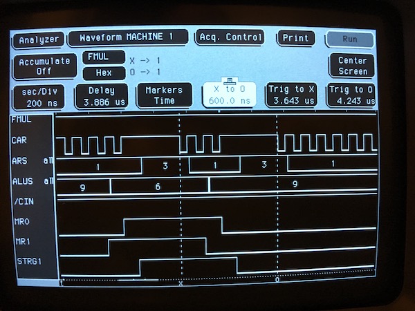
This is a portion of the multiply dealing with the a string of two consecutive 1s on the multiplier. The clocking and state machine state bits look correct (note that AR clocks falling edges). A four-cycle pause is inserted in the AR clock whenever the state-machine dictates either an add or a subtract is to occur, in order to allow for propagation time through the ALUs. The AR and ALU function selects also look correct: AR 1 for shift, 3 for load, and ALU 6 for subtract, 9 for add. Marker X here should be clocking in a subtraction at the start of the string, followed by two shifts, then an add at marker O at the end of the string.
But the ALU CIN control signal looks incorrect -- it is held high throughout the multiply, but should be driven low for the subtraction at marker X. This means the ALU function actually being selected is A-B-1 instead of A-B, which would produce the results seen above (the first subtract borrows an extra 1 all the way across the partial product, then subsequent subtracts borrow from the resulting 1s on the right). So it looks like the logic that generates CIN needs a look:
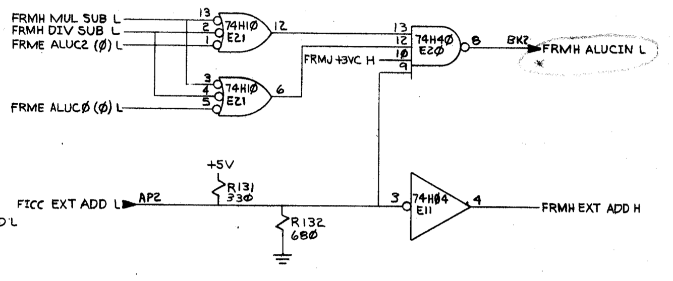
Stepping through the multiply with the KM11 in single-clock-transition mode, arriving at the first subtract, FRMH MUL SUB L is asserted low to pin 3 of E21, but pin 6 does not go high. Looks like a failed gate; pulled the part, put in a socket, and put a replacement 74H10 on order. All for now!
PDP-11/45: Diagnostics XII - FP11 FPU, cont.
Sun 30 October 2016 by Fritz MuellerSome spare 74194 arrived in the mail; popped one in to the socket I had prepared at E15 on the FRL board, and the FP add/subtract problem is fixed. The following FP11 diagnostics now pass:
| Diagnostic | Description | Status |
|---|---|---|
| CFPAB0.BIC | LDFPS,STFPS,SETI,SETL,SETF,SETD,CFCC | pass |
| CFPBB0.BIC | STST | pass |
| CFPCD0.BIC | LDF,LDD,STF,STD | pass |
| CFPDC0.BIC | ADDF,ADDD,SUBF,SUBD | pass |
| CFPEB0.BIC | CMPF,CMPD | pass |
| CFPFB0.BIC | MULF,MULD | pass |
| CFPGC0.BIC | DIVF,DIVD | pass |
| CFPHB0.BIC | CLR,TST,ABS,NEG | pass |
| CFPIB0.BIC | LDCDF,LDCFD,STCFD,STCDF | pass |
| CFPJB0.BIC | LDCJX,STCXJ | pass |
| CFPKB0.BIC | LDEXP | pass |
| CFPMB0.BIC | MAINT | pass |
...which is almost everything. The last failing diagnostic is CFPLB0, which tests MODF and MODD. Set up a similar test program for this instruction:
1 2 3 4 5 6 7 8 9 10 11 12 13 14 15 16 17 18 19 20 | 000000 AC0=%0
000001 AC1=%1
000000 .ASECT
001000 .=1000
001000 170011 START: SETD ;SET DOUBLE PRECISION MODE
001002 172467 000020 LDD D1,AC0 ;FETCH FIRST OPERAND FROM D1
001006 172567 000024 LDD D2,AC1 ;FETCH SECOND OPERAND FROM D2
001012 171401 MODD AC1,AC0 ;MOD (FRAC IN AC0, INT IN AC1)
001014 174067 000026 STD AC0,D3 ;STORE FRAC TO D3
001020 174167 000032 STD AC1,D4 ;STORE INT TO D4
001024 000000 HALT
001026 040200 000000 000000 D1: .WORD 040200,000000,000000,000000 ;1.0
001034 000000
001036 040300 000000 000000 D2: .WORD 040300,000000,000000,000000 ;1.5
001044 000000
001046 000000 000000 000000 D3: .WORD 000000,000000,000000,000000
001054 000000
001056 000000 000000 000000 D4: .WORD 000000,000000,000000,000000
001064 000000
001000 .END START
|
This does show a problem: after exection, the integer result at D4 seems correct, but the fractional result in D3 is incorrect (037777 177777 177777 177777). Verified the correct microflow with the KM11.
Stopped in microstate MOD.22, and examined ALUs on FRL where the fractional result is masked. ALU function selects (for A & ~B) and B inputs (all zeros for mask) look correct throughout. A inputs, however, are all ones except the least significant bit, which seems incorrect. All for now -- will dig a little deeper on the microcode flows and follow up on this lead next time...
PDP-11/45: Diagnostics XI - FP11 FPU, cont.
Sun 23 October 2016 by Fritz MuellerWrote some small test programs to investigate FP add/subtract. Turns out that single-precision add/subtract works fine, but double-precision results come back with some erroneous bits set in the fraction. Here's the test code I ended up using for troublshooting -- when executed on my machine, bits 24 and 25 end up incorrectly set in the result at D3:
1 2 3 4 5 6 7 8 9 10 11 12 13 14 15 16 17 | 000000 AC0=%0
000001 AC1=%1
000000 .ASECT
001000 .=1000
001000 170011 START: SETD ;SET DOUBLE PRECISION MODE
001002 172467 000014 LDD D1,AC0 ;FETCH FIRST ADDEND FROM D1
001006 172567 000020 LDD D2,AC1 ;FETCH SECOND ADDEND FROM D2
001012 172100 ADDD AC0,AC1 ;ADD THEM (RESULT IN AC1)
001014 174167 000022 STD AC1,D3 ;STORE RESULT TO D3
001020 000000 HALT
001022 040200 000000 000000 D1: .WORD 040000,000000,000000,000000 ;0.5
001030 000000
001032 040200 000000 000000 D2: .WORD 040000,000000,000000,000000 ;0.5
001040 000000
001042 000000 000000 000000 D3: .WORD 000000,000000,000000,000000
001050 000000
001000 .END START
|
So, the usual procedure: KM11 in the floating point slot, and FRL (where these bits are handled) out on extenders. First step is to verify the microcode sequencing with the KM11 and front panel, and it looks good. In particular, the FPU is sequencing through states ADD.04 and ADD.06 per expectation for double-precision, branching correctly for non-zero operands, and taking the equal exponents branch through ADD.24 (refer to page FLOWS 8 of the FP11 engineering drawings).
Next, stopped in state ADD.38, where the fraction addition occurs, and scanned the inputs and outputs of all the 74181 bitslice ALUs with a logic probe. Bit 28 of the A input to the FALU (E16 pin 2, refer to page FRLJ of the FP11 engineering drawings) is incorrectly set. This is arriving via the AR register.
The value in the AR register is originally fetched from the register scratchpad, then flows through QR, BR, and the FALU during microstates ADD.04, ADD.06, and ADD.02. Some more stepping and logic probe work showed that the fraction values are correct along these paths through these states. So it looks like AR itself may be at fault.
Set up the logic analyzer on E15, which is a 74194 shift-register that holds bits 28-31 of AR. It looks like it is indeed faulty:
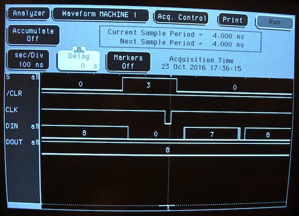
Here we can see what should be a broadside load: positive CLK edge, S0 and S1 both asserted, and inputs of all zeros. But the output sticks brokenly at 8. Pulled this shift register, soldered in a socket, and put a replacement and a couple of spares on order. All for now, until the parts arrive.
PDP-11/45: Diagnostics X - FP11 FPU, cont.
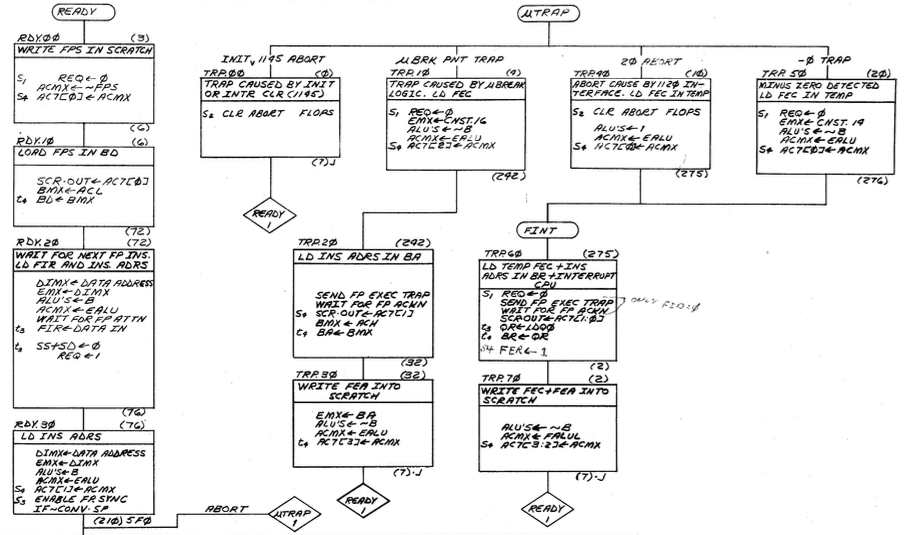
Sat 01 October 2016 by Fritz MuellerOkay, here's the dig in on the FP11 STST diagnostic failure. As detailed previously, I'd been seeing an incorrect FEC after executing a small test program to generate a minus-zero condition. I'd verified that the microcode sequence was per expectation, and that the correct FEC was being stored and retrieved from AC7[1:0] in microstates TRP.50 and the start of TRP.60.
The end of TCP.60 and all of state TRP.70 are used to move the FEC and FEA from AC7[1:0] to AC7[3:2] via QR and BR, and something was going awry here. Since the nominal FEC is octal 14, I decided just to trace the four least significant bits. Consulting the engineering drawings, the nominal flow of these bits through logic on the FRL during these states would be:
| Function | Package | Dir | Pin:Level | Microstate | |||
|---|---|---|---|---|---|---|---|
| ACi<03:00> | E85 | out | 11:H | 9:H | 7:L | 5:L | TRP.60 (2) |
| QR<06:03> | E74 | in | 3:H | 4:H | 5:L | 6:L | |
| out | 15:H | 14:H | 13:L | 12:L | TRP.70 (3) | ||
| BR<07:04> | E75 | in | 13:H | 12:H | 4:L | ||
| out | 15:H | 10:H | 2:L | ||||
| BR<03:00> | E87 | in | 5:L | ||||
| out | 7:L | ||||||
| FALU<07:04> | E77 | in | 20:H | 22:H | 1:L | ||
| out | 11:L | 10:L | 9:H | ||||
| FALU<03:00> | E89 | in | 18:L | ||||
| out | 13:H | ||||||
| ACMX<03:02> | E83 | in | 13:L | 3:L | |||
| out | 9:L | 7:L | |||||
| ACMX<01:00> | E84 | in | 13:H | 3:H | |||
| out | 9:H | 7:H | |||||
| ACi<03:00> | E85 | in | 12:L | 10:L | 6:H | 4:H | |
Note that the bit values are inverted here by the FALU, since the reigster file used on the FP11 has inverting outputs.
Threw the FRL out on extenders and starting verifying the chart above with a logic probe. Surprisingly, everything probed out correctly (?!) Reset and ran the test program and verified that the bug had gone away. Hmmm... My only guess here is that there was some dust or a whisker shorting some of the pins that I dislodged with the logic probe, or perhaps an oxidized board conection. In any case, it seems to work robustly now. Of the FP11 diagnostics, the following now pass:
| Diagnostic | Description | Status |
|---|---|---|
| CFPAB0.BIC | LDFPS,STFPS,SETI,SETL,SETF,SETD,CFCC | pass |
| CFPBB0.BIC | STST | pass |
| CFPCD0.BIC | LDF,LDD,STF,STD | pass |
| CFPHB0.BIC | CLR,TST,ABS,NEG | pass |
| CFPKB0.BIC | LDEXP | pass |
CFPDB0.BIC, which tests floating point adds/subtracts, is failing. All for now -- on to debugging add/subtract next time...
PDP-11/45: H720E teardown and inspection
Sun 18 September 2016 by Fritz MuellerStarted in on the H720E power supply that is part of RK05 storage system. Just initial teardown, cleaning, and inspection for obviously failed parts. Looks pretty good, though there is a lot of dust and grime because this unit lost its top cover plate somewhere over the years (I'll have to build some sort of replacement).
There are a couple of 22,000 mFD 50v electrolytic caps here that I'll try reforming before hitting them at full power, since they've been sitting idle for upwards of 30yrs! Also, one obviously leaking 330 mfd axial on regulator board, so I'll replace this and all its identical twins. Parts on order...


PDP-11/45: Diagnostics IX - FP11 FPU, cont.
Sat 10 September 2016 by Fritz MuellerDid a lot of reading on the FP11 design. A few interesting notes that are buried in the maintenance manual:
-
When debugging FP11 microcode with a KM11 in single-microstep mode, the 11/45 front panel microcode display shows the address of the next microinstruction, NOT the current microinstruction. This is because the stop-point for single microinstruction is at a point between T2 and T3, just after the next microinstruction addr has been calculated. This is different behavior than the 11/45 CPU front panel microaddress display.
-
There's a note in the maintenance manual that explicitly cautions that when using extender boards for debug, the RC maintenance clock should be used, and set with period >50ns. I had not been doing similar while debugging the KB11-A CPU, and maybe this explains the occasional different behavior I'd see when throwing boards out on extenders... In particular, I had seen this when debugging a spare CPU GRA; next time I return to that board I will try the CPU RC clock.
Okay, so here's my first simple test program for STST:
1 2 3 4 5 6 7 8 9 | 000000 AC0=%0
000000 .ASECT
001000 .=1000
001000 170127 044000 START: LDFPS #044000 ;FID+FIUV
001004 172467 000004 LDF NEGZ,AC0 ;LOAD A MINUS-ZERO
001010 170300 STST R0 ;STORE FEC TO R0
001012 000000 HALT
001014 100000 000000 NEGZ: .WORD 100000,000000 ;MINUS-ZERO
001000 .END START
|
This would be expected to produce the 000014 "Floating Undefined Variable" (minus-zero) exception code in R0, but I see an incorrect value of 177417. Using the KM11 on the FPU shows the -0 trap and STST microstate flow is per expectation.
Put the FRL out on the extender and started stepping the microcode, examining the state of the pins at the AC register file along the way. In the -0 trap flow, the FEC code 000014 presented (inverted) at TRP.50 via the EALU, and subsequently retrieved at TRP.60 looks correct. However, the value presented at TRP.70 via QR, BR, and the FALU does not. Out of time this weekend; Will have to chase signals back through those paths next time!
PDP-11/45: Diagnostics VIII - FP11 FPU
Sat 03 September 2016 by Fritz MuellerSlotted in FP11 spares that I hadn't tried previously, and this has produced some improved results -- returning to diagnostic CKBME0 (11/45 traps) this now passes with the floating point installed. Additionally, diagnostic CFPAB0 passes.
CFPBB0 and CFPCD0, however, are failing. Unfortunately, the source code for these is not available in the PDP-11 diagnostics database at retrocmp. The names of the diagnostics tell which instructions they are testing, though. CFPBB0 is annotated as testing the STST instruction. Rather than work through disassembling the rather lengthy diagnostics, I'll probably just write some simple test programs around the STST instruction for next time. In the meantime, I'll do some reading on the FP11 in preparation for microcode-step debug.